Vapor sheath for liquid dispensing nozzle

a liquid dispensing nozzle and vapor sheath technology, which is applied in the direction of lighting and heating apparatus, combustion types, instruments, etc., can solve the problems of clogging or blocking the nozzle of solid materials, undesirable situations, and evaporation of carrier solvents, so as to prevent or minimize prevent the clogging or blocking of the nozzle, and prevent the evaporation of solvents

Active Publication Date: 2011-02-17
GLAXO SMITHKLINE LLC
View PDF6 Cites 0 Cited by
  • Summary
  • Abstract
  • Description
  • Claims
  • Application Information

AI Technical Summary

Benefits of technology

[0006]The present disclosure provides a device for a fluid dispensing nozzle that prevents or minimizes the evaporation of a solvent in the vicinity of the nozzle end.
[0007]The present disclosure provides a porous or solid band that can be placed around the end of the dispensing nozzle. The fluid in the dispensing nozzle comprises the ingredient that is to be delivered to the target (for example, in a pharmaceutical application, the active agent), and one or more carrier solvents. The same carrier io solvent or carrier solvents that are present in the fluid being dispensed through the nozzle are supplied to the band in the manner described below. A situation is created where the band is saturated, or nearly so, with the same solvent or solvents within the dispensing nozzle, so that it creates a sheath of vapor in the local environment around the nozzle end. The vapor sheath can be at the nozzle end, and / or can surround the dispensing end of the nozzle. The vapor sheath has been found to prevent the evaporation of the solvent at the nozzle end, thus preventing the clogging or fouling of the nozzle.
[0008]Thus, in one embodiment, the present disclosure provides a device for dispensing a fluid onto a target. The device comprises a dispensing nozzle having an end for emitting the fluid onto the target, wherein the fluid comprises a solvent. The device further comprises a band having a hollow interior and an inner surface. The band is positioned so that the end of the dispensing nozzle is in the hollow interior, and so that a gap is formed between the inner surface of the band and the end of the dispensing nozzle. The band also has the solvent present thereon. The solvent present on the band evaporates into the gap to assist in the prevention of evaporation of the solvent at said end of the dispensing nozzle.

Problems solved by technology

There are many environmental circumstances that can cause evaporation of the carrier solvent.
This can create an undesirable situation, because when the carrier solvent evaporates, solid material can form at the end of the dispensing nozzle.
This solid material fouls or clogs the nozzle.

Method used


Image

  • Vapor sheath for liquid dispensing nozzle
  • Vapor sheath for liquid dispensing nozzle
  • Vapor sheath for liquid dispensing nozzle

Examples


Embodiment Construction

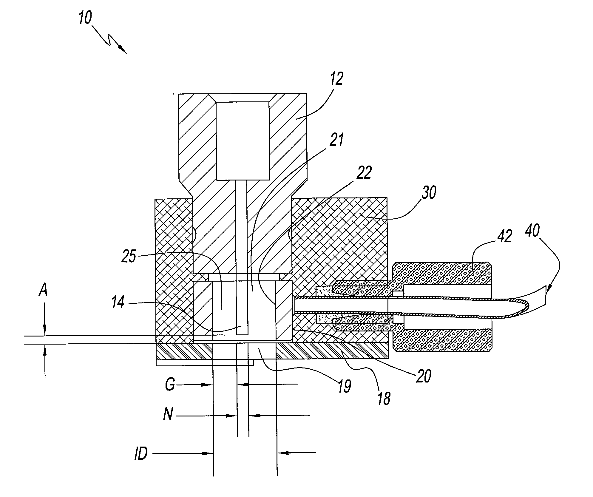
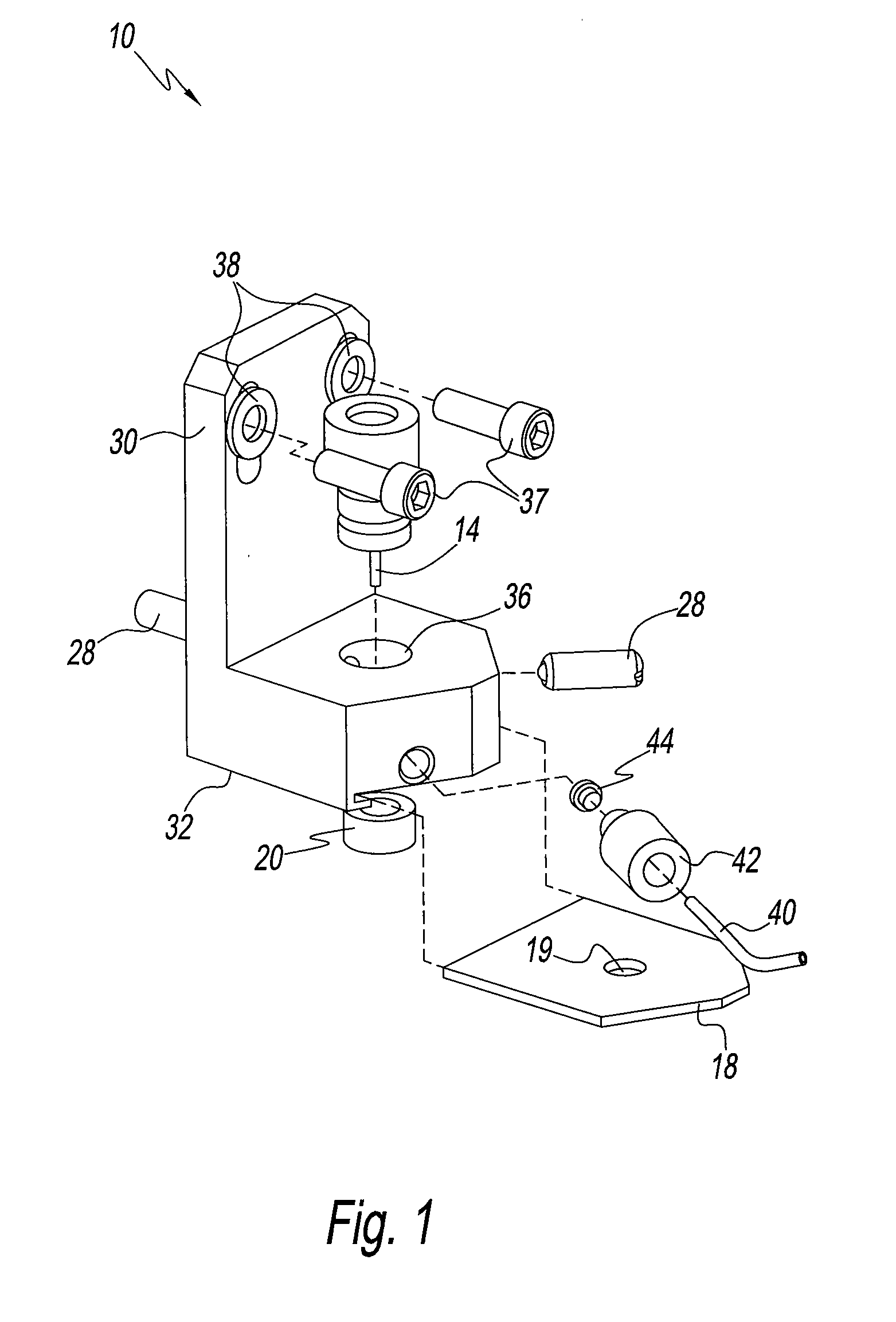
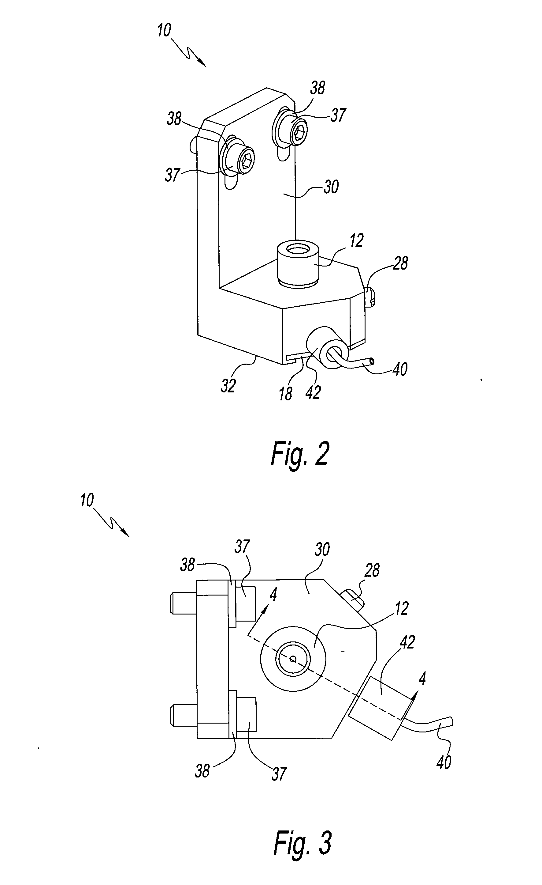
[0016]Referring to the Figures, dispensing nozzle mount assembly 10 is shown. Assembly 10 comprises nozzle 12, and band 20. Band 20 has a hollow interior 21, and an inner surface 22. As shown and as described in greater detail below, nozzle 12 is placed in the top end of a hole 36 through mount 30, and band 20 is mounted in a counterbore at the bottom end of hole 36, so that an end 14 of nozzle 12 is in hollow interior 21. A gap 25 is thus formed between end 14 of dispensing nozzle 12 and inner surface 22. A fluid (not shown), which comprises one or more solvents, and usually at least one other ingredient, such as a pharmaceutical active or a polymer, is dispensed through nozzle 12, and out the bottom 32 of mount 30, onto a target (not shown).

[0017]Band 20 is saturated with the same solvent or solvents that are dispensed through nozzle 12, in liquid form, and in the manner discussed below. The solvent(s) are replenished as necessary in order to keep band 20 at the desired level of s...


PUM


Abstract

The present disclosure provides a device for preventing the fouling of a liquid dispensing nozzle. The end of the dispensing nozzle is placed In a hollow interior of a band carrying the same solvents that are dispensed by the nozzle. The solvent on the band evaporates into a gap between the ring and the dispensing nozzle, thus providing a vapor sheath or environment that helps to prevent the fouling of the dispensing nozzle.

Description

CROSS-REFERENCE TO RELATED APPLICATIONS[0001]The present application claims priority to U.S. Provisional Patent Application No. 61 / 232,898, filed on Aug. 11, 2009.BACKGROUND OF THE DISCLOSURE[0002]1. Field of the Disclosure[0003]The present disclosure relates to a device for improving the dispensing of fluids is from a nozzle or similar device. In particular, the present disclosure relates to a device that creates a sheath of solvent vapor in the vicinity of the dispensing end of the nozzle to prevent the fouling or clogging of the nozzle by materials deposited on the nozzle end as a result of solvent evaporation.[0004]2. Description of the Related Art[0005]In the art of fluid dispensing technology, it is often required to dispense a material that is dissolved in a carrier solvent. There are many environmental circumstances that can cause evaporation of the carrier solvent. This can create an undesirable situation, because when the carrier solvent evaporates, solid material can form...

Claims


Application Information

Patent Timeline
Patent Type & Authority Applications(United States)
IPC IPC(8): B67D7/00B67D7/76B67D7/82
CPCA61M11/00B05B15/025B05B15/50B05B15/55B05D1/02
Inventor CLARKE, ALLAN J.FIESSER, FREDERICK H.MCHUGH, JAMES A.
Owner GLAXO SMITHKLINE LLC
Why Eureka
Try Eureka