Lens-mounted light emitting unit

a technology of light emitting unit and lens, which is applied in the direction of instruments, lighting and heating apparatus, semiconductor devices for light sources, etc., can solve the problems of inability to centrally place one led element, color unevenness, color unevenness, etc., and achieves improved color mixing properties, poor color mixing properties, and increased diffusion

Inactive Publication Date: 2011-02-17
PANASONIC CORP
View PDF7 Cites 27 Cited by
  • Summary
  • Abstract
  • Description
  • Claims
  • Application Information

AI Technical Summary

Benefits of technology

[0006]In order to solve the above-described problems, the object of the present invention is to enable narrow-angle light distribution and improve color mixing properties in a lens-mounted light emitting unit comprising LED elements of multiple light colors.Means for Solving the Problem
[0008]According to this structure, sufficient color mixing of light incident on the upper incident surface is achieved while enabling narrow-angle light distribution by a condenser lens, making it possible to improve the color mixing properties of the light emitting unit, because, assuming an arbitrary contact point between the side incident surface and the upper incident surface, and that light from an LED element farthest from the contact point is refracted at the contact point to form a light path intersecting the emitting surface at an intersection point, the emitting surface inside a circle with a radius formed by continuously connecting such intersection points has a diffusion angle larger than the diffusion angle of the emitting surface outside the circle.
[0010]According to this structure, the case where the upper incident surface is a flat surface perpendicular to a normal line of the base plate allows good color mixing properties in lens center, so that by reducing diffusion of such area, it is possible to improve the light collecting properties.
[0012]According to this structure, the case where the upper incident surface is a convex surface perpendicular to a normal line of the base plate causes the light substantially parallel to the lens center axis to increase, resulting in light collection offset from the lens center axis and thus in most poor color mixing properties. However, the color mixing properties can be improved with a minimum diffusion angle by increasing the diffusion in a central area of the circle and by reducing the diffusion in a peripheral area of the circle.

Problems solved by technology

However, if multiple LED elements are used, it is not possible to centrally place one LED element.
Thus, if multiple single-color LED elements are used for the condenser lens, the positions of the LED elements of multiple light colors are offset on one side, respectively, relative to the lens center axis, so that paths of light emitted from the respective LED elements and passing through the convex incident surface are asymmetrical relative to the lens center axis, causing color unevenness.
Further, even if the convex incident surface is flat, such axial asymmetry remains, causing color unevenness.

Method used


Image

  • Lens-mounted light emitting unit
  • Lens-mounted light emitting unit
  • Lens-mounted light emitting unit

Examples


Embodiment Construction

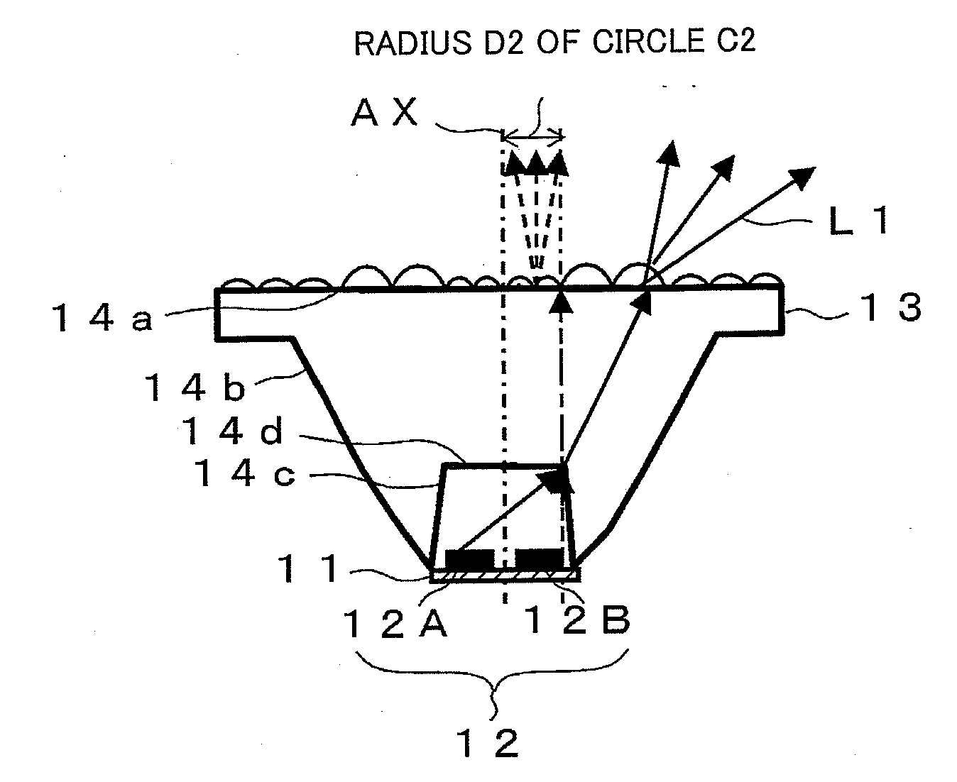
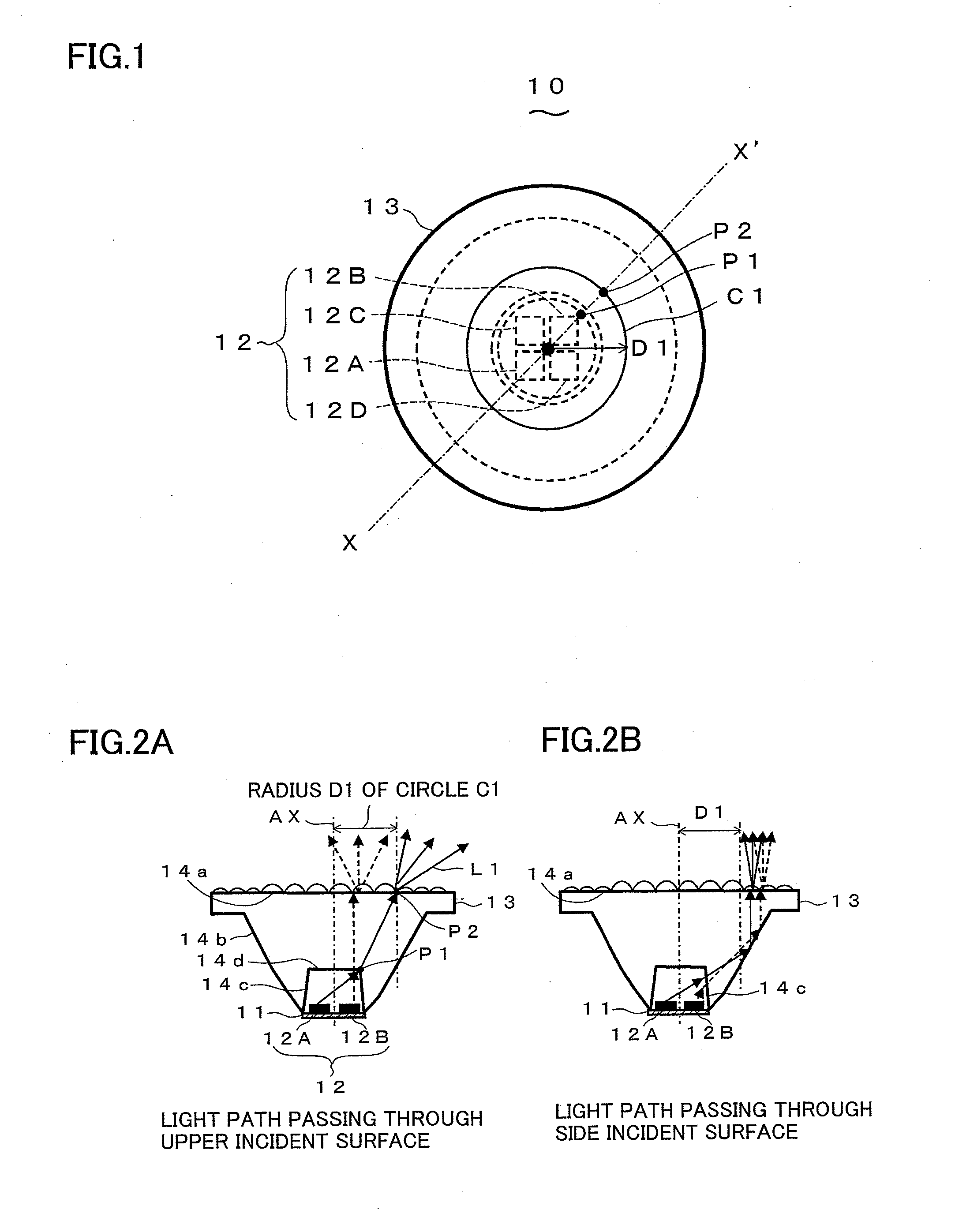
[0030]Hereinafter, a lens-mounted light emitting unit according to a first embodiment embodying the present invention will be described. FIG. 1 shows a top face of the lens-mounted light emitting unit of the present embodiment, while FIGS. 2A and 2B show cross-sections of the unit. In the Figures, hatching of the lens cross-sections is omitted (the same applies hereinafter). The lens-mounted light emitting unit with lens 10 comprises: a base plate 11; multiple LED elements 12A to 12D (collectively referred to as LED elements 12) placed on the base plate 11; and a lens unit 13 having a shape of a body of revolution about a normal line of the base plate 11 as a symmetry axis of revolution which passes through substantially the center of gravity of the multiple LED elements 12. The multiple LED elements 12 include LED elements 12 of multiple light colors, while the lens unit 13 color-mixes and emits the light from the LED elements 12.

[0031]The base plate 11 is a plate using glass epoxy...


PUM


Abstract

In a lens-mounted light emitting unit comprising LED elements of multiple light colors, narrow-angle light distribution is enabled, and color mixing properties are improved. The lens-mounted light emitting unit 10 comprises LED elements 12 (12A to 12D) of multiple light colors placed on a base plate 11, and a lens unit 11 having a shape of a body of revolution to color-mix and emit the light from the LED elements 12. Assuming an arbitrary contact point P1 between the side incident surface 14c and the upper incident surface 14d of the lens unit 13, and that light from an LED element 12A farthest from the contact point P1 is refracted at the contact point P1 to form a light path L1 intersecting the emitting surface 14a at an intersection point P2, the emitting surface 14a inside a circle C1 formed by continuously connecting such intersection points has a diffusion angle larger than the diffusion angle of the emitting surface 14a outside the circle C1. This enables narrow-angle light distribution, and makes it possible to improve color mixing properties.

Description

TECHNICAL FIELD[0001]The present invention relates to a lens-mounted light emitting unit using a lens to color-mix light emitted from LED elements of multiple light colors such as red, blue and green.BACKGROUND ART[0002]Conventionally, as described, for example, in Japanese Laid-open Patent Publication Hei 10-290028, a device for color-mixing light from single-color LEDs such as red, blue and green without color unevenness is known, in which all the light emitted from the LEDs is projected on a reflector for multiple reflection so as to extract only indirect light, thereby improving the color mixing properties of light. Further, as described, for example, in Japanese Laid-open Patent Publication 2002-133032, a device is proposed, in which a light guide member and a diffusion layer are added so as to emit light from each LED in one direction by using the total reflection of the light guide member, and to uniformly increase the scattering properties by using the diffusion layer, there...

Claims


Application Information

Patent Timeline
Patent Type & Authority Applications(United States)
IPC IPC(8): H01L33/08F21V5/00F21V5/04F21V13/04F21Y101/02G02B3/00G02B3/08H01L33/00H01L33/58H01L33/60
CPCF21V5/04F21V7/0091F21Y2101/02G02B3/0043G02B19/0028H01L25/0753H01L33/58G02B19/0066G02B5/02H01L2924/0002F21Y2115/10H01L2924/00
Inventor SEKII, HIROYUKIMATSUBAYASHI, YOKOTANAKA, KENICHIRO
Owner PANASONIC CORP
Why Eureka
Try Eureka