
Microfluidic and nanofluidic devices, systems, and applications

Inactive Publication Date: 2011-02-17
INTEGENX
View PDF107 Cites 101 Cited by
  • Summary
  • Abstract
  • Description
  • Claims
  • Application Information

AI Technical Summary

Benefits of technology

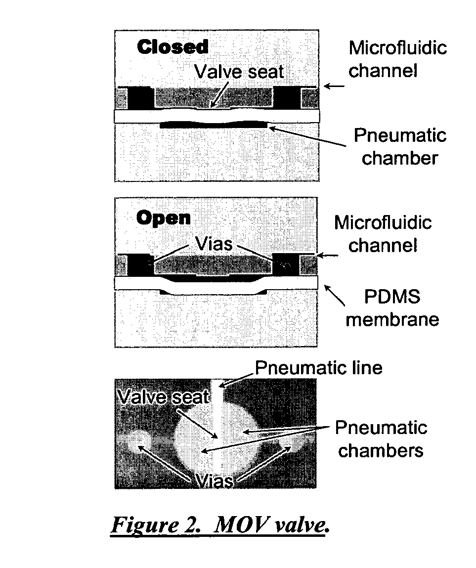
[0011]In one aspect this invention provides a microfluidic device comprising: a microfluidic layer, an actuation layer and elastomer layer sandwiched between them, wherein: the microfluidic layer comprises at least three microfluidic channels converging at a nexus and separated by discontinuities that interrupt the flow of fluid in said at least three microfluidic channels; the actuation layer comprises at least one actuation channel opening into a valve chamber, which valve chamber is disposed opposite the nexus; and wherein displacement of said elastomeric membrane modulates fluid flow across said at least three microfluidic channels, whereby a diaphragm valve is formed. In one embodiment, the elastomeric membrane simultaneously modulates fluid flow across said at least three microfluidic channels. In another embodiment, the elastomeric membrane prevents fluid flow across said at least three microfluidic channels. In another embodiment, the elastomeric membrane incompletely inhibits fluid flow across said at least three microfluidic channels. In another embodiment, diaphragm valve further comprises a vias layer. In another embodiment, the application of pressure or a vacuum to sai

Problems solved by technology

In the absence of standards controlling external dimensional form factors, the nature of the upstream and downstream external interface, and the length, cross-sectional geometry, and diameter of the internal microfluidic pathways, such microfluidic devices often proved incompatible with one another and with existing upstream purification and downstream analytical devices.
More complex processes are created by docking two microdevices and transferring the processed samples.

Method used


Image

  • Microfluidic and nanofluidic devices, systems, and applications
  • Microfluidic and nanofluidic devices, systems, and applications
  • Microfluidic and nanofluidic devices, systems, and applications

Examples


Embodiment Construction

[0090]In one aspect this invention provides guidance on the use of programmable microfluidic circuits and devices to process biochemical or chemical samples. In some embodiments microfluidic processes are connected with inputs or sample volumes of milliliter or centiliter scale. Further chemical and biochemical processes and the integration of multiple processes are disclosed. In some embodiments, microfabrication of microvalves with different designs are taught.

[0091]In certain embodiments the microfluidic devices of this invention comprise a microfluidic layer, an actuation layer and an elastomeric membrane sandwiched therebetween. The fluidics layer comprises fluidic channels adapted to allow the flow of liquid. In certain embodiments, the fluidics channels are located on the surface of the microfluidics layer that touches the elastomeric membrane. In this embodiment, an open channel, furrow or groove can be etched into the surface of the layer. In other embodiments, the channel ...


PUM

PropertyMeasurementUnit
Magnetic fieldaaaaaaaaaa

Abstract

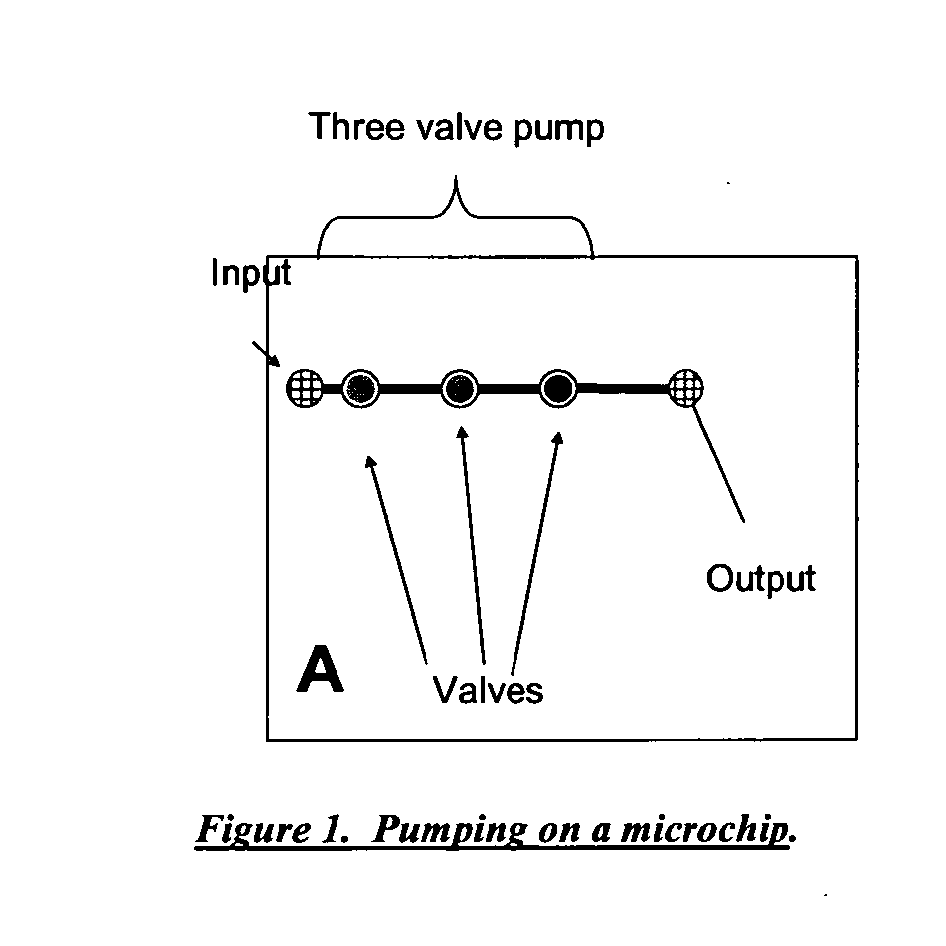
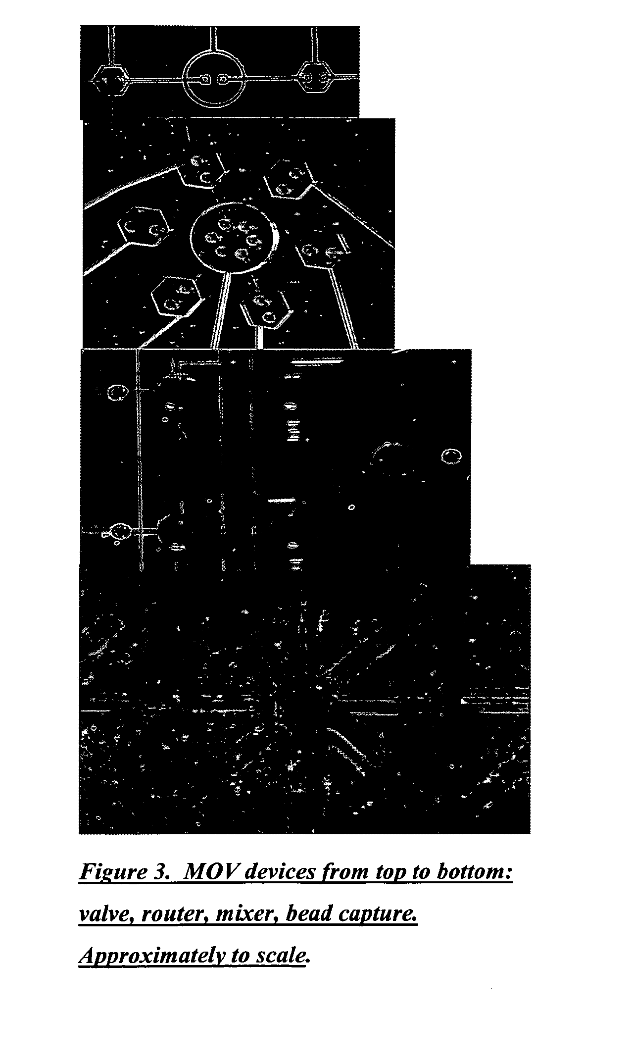
The present invention discloses the integration of programmable microfluidic circuits to achieve practical applications to process biochemical and chemical reactions and to integrate these reactions. In some embodiments workflows for biochemical reactions or chemical workflows are combined. Microvalves such as programmable microfluidic circuit with Y valves and flow through valves are disclosed. In some embodiments microvalves of the present invention are used for mixing fluids, which may be part of an integrated process. These processes include mixing samples and moving reactions to an edge or reservoir for modular microfluidics, use of capture regions, and injection into analytical devices on separate devices. In some embodiments star and nested star designs, or bead capture by change of cross sectional area of a channel in a microvalve are used. Movement of samples between temperature zones are further disclosed using fixed temperature and movement of the samples by micropumps.

Description

CROSS-REFERENCE[0001]This application claims the benefit of U.S. Provisional Application No. 60 / 899,630 “Microfluidic and nanofluidic devices, systems, and applications” filed Feb. 5, 2007, which application is incorporated herein by reference, in its entirety.STATEMENT AS TO FEDERALLY SPONSORED RESEARCH[0002]Aspects of this invention were made with government support under one or more of Project No. W911SR-04-P-0047 awarded by the Department of Defense, Grant No. 5R01HG003583 awarded by the NIH, Contract No. NBCHCO50133 awarded by HSARPA, Order No. TTA-1-0014 (Agreement No. W81XWH-04-9-0012) awarded by HSARPA. The government has certain rights in this invention.BACKGROUND OF THE INVENTION[0003]A variety of microfluidic devices of disparate, design have been developed in the past often with the goal of reducing sample volume requirements in bioanalytical methods, integrating multiple steps into automated processes, integrating sample preparation and analysis, and connecting to the f...

Claims


Application Information

Patent Timeline
IPC IPC(8): C12P19/34B01L3/00C07H21/04C07K14/00
CPCB01L2300/0896C12Q1/686B01L2400/0481B01L2400/0655B82Y30/00F16K99/0001B01L3/502715B01L3/50273B01L3/502761B01L7/52B01L7/525B01L2200/028B01L2200/0668B01L2200/10B01L2300/0816B01L2300/0867B01L2300/0874B01L2300/088B01L2300/0887B01L2300/1827B01L3/502738B01L2400/0622B33Y80/00B01L3/02B82Y35/00G01N35/00G01N35/08
Inventor JOVANOVICH, STEVAN BOGDANBLAGA, IULIU IOANBORONKAY, ALLENHORN, JOANNEVAN NGUYEN, MICHAELNIELSEN, WILLIAM D.VANGBO, MATTIAS
Owner INTEGENX
Learn More