

Data transmission/reception method
- Summary
- Abstract
- Description
- Claims
- Application Information
AI Technical Summary
Benefits of technology
Problems solved by technology
Method used
Image

Examples
Embodiment Construction
[0041]Embodiments of the present invention will now be described in detail with reference to the accompanying drawings.
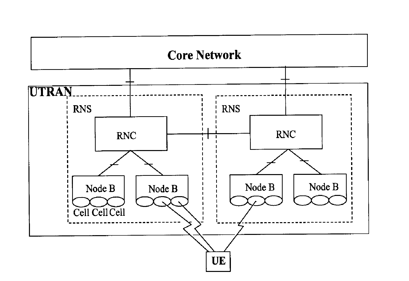
[0042]Although a UE (User Equipment) is described in FIGS. 4 and 5, the UE may be called a terminal, an ME (Mobile Equipment), or an MS (Mobile Station). The UE may be a mobile device having a communication function such as a mobile phone, a PDA, a smart phone, notebook computer, etc., or may be a device that cannot be portable such as a PC or a vehicle-mounted device. In FIGS. 4 and 5, a UTRAN (UMTS Terrestrial Radio Access Network) is shown, but the UTRAN may be a wireless access system such as CDMA, CDMA2000, WCDMA, IEEE 802-16, etc.
[0043]FIG. 4 is a flow chart illustrating the process of a discontinuous reception method according to a first exemplary embodiment of the present invention.
[0044]As shown in FIG. 4, a first exemplary embodiment of the present invention features that when a UE 100 operating according to a first discontinuous reception period, e.g., a ...
PUM
 Abstract
Description
Claims
Application Information