Grouted Tubular Energy-Dissipation Unit

a technology of energy dissipation unit and grouted tubular, which is applied in the direction of structural elements, building components, shock-proofing, etc., can solve the problems of high cost and low reliability, inconvenience in installation, maintenance or replacement, and high cost, so as to increase friction, dissipate and absorb energy, and high manufacture precision

Inactive Publication Date: 2011-02-24
TONGJI UNIV
View PDF5 Cites 13 Cited by
  • Summary
  • Abstract
  • Description
  • Claims
  • Application Information

AI Technical Summary

Benefits of technology

[0007]In order to overcome the above-mentioned drawbacks, the present invention provides an energy-dissipation unit that is convenient to provide maintenance and be replaced, simple to be manufactured and be installed, and has high performance with low cost. The present invention can provide earthquake effect-reduction solution for newly built construction and existing construction, and can serve as load-bearing structural member of buildings in service.
[0012]Preferably, two edges of the metal skin overlaps and can slide relatively.
[0021]The advantages of the present invention are illustrated as follows. The present invention utilizes the prestress produced by the expansive cement grout so as to increase the friction between the expansive ring and the steel tubes. In normal condition, the present invention can bear large axial load and is as rigid as ordinary brace. In case of earthquake, the present invention can dissipate and absorb energy via the relative slide between the inner tube and the outer tube. The present invention does not require high manufacture precision, can save steel, has low cost, and can be manufactured in standard mass production. When the present invention is damaged in earthquake, it is only need to replace the grouted tubular energy-dissipation unit, which is very convenient.
[0022]The present invention can replace the existing friction energy dissipation brace, VD, and BRB. Grouted tubular connections have been used in the construction engineering, but only used for steel tube connections. It has not been realized that the grouted tubes can be used for the energy dissipation of multi-store buildings, high-rise buildings and space structure. The present invention provides an earthquake effect-reduction technology for both newly-built construction and existing construction, which is easy to be manufactured and has low cost.

Problems solved by technology

The conventional seismic resistant design focuses on “resisting”, which has drawbacks of high cost and low reliability.
The conventional energy dissipation brace is to connect dissipation element or damper to the ordinary brace, or is made of high ductile metal materials, which has drawbacks of high cost, inconvenience to be installed, get maintenance or be replaced, and high precise requirement in manufacturing and constructing.

Method used


Image

  • Grouted Tubular Energy-Dissipation Unit
  • Grouted Tubular Energy-Dissipation Unit
  • Grouted Tubular Energy-Dissipation Unit

Examples


Embodiment Construction

[0030]The present invention is further explained in detail according to the accompanying drawings.

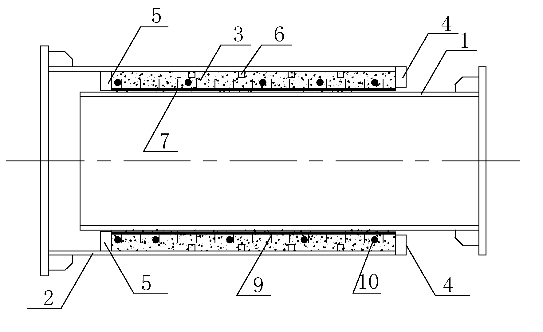
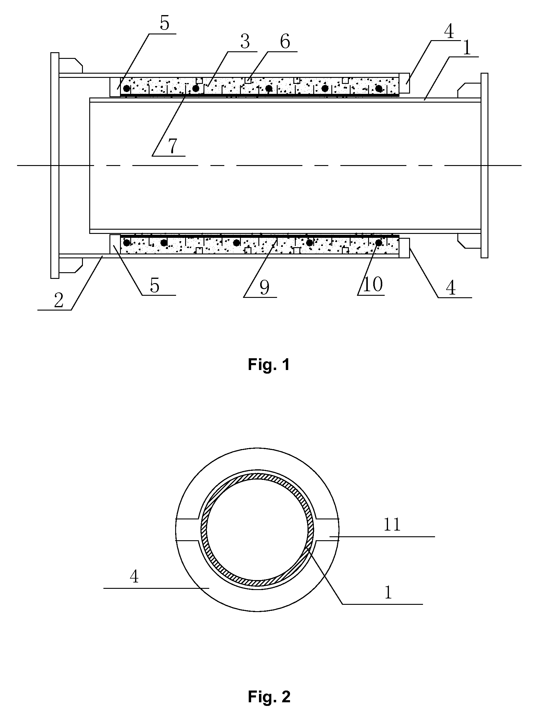
[0031]Referring to FIG. 1 of the drawings, a grouted tubular energy-dissipation unit according to the first embodiment comprises an inner tube 1 and an outer tube 2. The inner tube 1 is coaxially inserted into the outer tube defining a lapping portion between the inner tube and the outer tube. The outer surface of the inner tube 1 and the inner surface of the outer tube 2 are prepared by sandblasting and shot blasting. An outer annular plate 4 is provided on an outer end of the lapping portion of the inner tube 1 and the outer tube 2; an inner annular plate 5 is provided on an inner end of the lapping portion of the inner tube 1 and the outer tube 2, as shown in FIG. 2. The outer annular plate 4 and inner annular plate 5 are fixedly connected with the outer tube 2. The inner annular plate 5, outer annular plate 4, the inner tube 1 and the outer tube 2 define a grouting cavity 3. The gro...


PUM

PropertyMeasurementUnit
structureaaaaaaaaaa
velocityaaaaaaaaaa
friction energyaaaaaaaaaa

Abstract

The present invention discloses a grouted tubular energy-dissipation unit comprising an inner tube and an outer tube. The inner tube is coaxially inserted into the outer tube defining a gap within a lapping portion of the tubes for receiving expansive cement grout. After solidified, the expansive cement grout forms an expansive ring. A prestress produced by the expansive cement grout increases the friction between the expansive ring and the tubes. In service, the present invention can transfer the axial force via the friction between the tubes and the expansive cement grout. In case of earthquake, the sliding friction between the tubes and the expansive cement grout can absorb energy. The present invention does not require high precise in manufacturing and constructing, saves steel and has low cost. It is only need to replace the grouted tubular energy-dissipation unit when the present invention is damaged in earthquake, which is very convenient.

Description

BACKGROUND OF THE PRESENT INVENTION[0001]1. Field of Invention[0002]The present invention relates to a brace of a building structure, and more particularly to an energy-dissipation unit used in the brace for reducing the destruction to buildings and constructions caused by earthquake.[0003]2. Description of Related Arts[0004]More and more multi-store buildings and high-rise buildings are constructed, so that seismic resistant design attracts continuous efforts from researchers. The conventional seismic resistant design focuses on “resisting”, which has drawbacks of high cost and low reliability. Therefore, a structure controlling technology is developed. The structure controlling technology includes active structure controlling technology and passive structure controlling technology. Energy dissipation brace is a common passive structure controlling technology, which can be used for the earthquake effect-reduction of newly built construction and existing construction.[0005]Ordinary ...

Claims


Application Information

Patent Timeline
Patent Type & Authority Applications(United States)
IPC IPC(8): E04B1/98E04H9/02
CPCE04H9/028E04H9/02E04H9/0237
Inventor JIANG, SHOU CHAOZHAO, YUAN YUANLI, GUO QIANGWANG, ZHENZHAO, XIAO LIN
Owner TONGJI UNIV
Why Eureka
Try Eureka