Control method of refrigerator

a technology of control method and refrigerator, which is applied in the direction of defrosting, domestic cooling apparatus, application, etc., can solve the problems of increasing temperature difference, affecting the smooth flow of refrigerants, and affecting the efficiency of refrigerant circulation, so as to facilitate the circulation of refrigerants and increase the temperature of low-temperature evaporators. , to achieve the effect of effective cooling operation

Active Publication Date: 2011-02-24
LG ELECTRONICS INC
View PDF4 Cites 40 Cited by
  • Summary
  • Abstract
  • Description
  • Claims
  • Application Information

AI Technical Summary

Benefits of technology

[0014]The refrigerant control method in accordance with the present invention can effectively perform a cooling operation by activating a fan at the completion of cooling of the low temperature storage compartment to facilitate the circulation of refrigerants and increase the temperature of the low temperature evaporator.
[0015]Moreover, the refrigerant control metho

Problems solved by technology

This leads to an increase of temperature difference between the low temperature evaporator and the high temperature evaporator, and a pressure in the low temperature evaporator becomes much lower than a pressure in the high temperature evaporator, eventually impeding a smooth flow of refrigerants from the low temperature evaporator to th

Method used


Image

  • Control method of refrigerator
  • Control method of refrigerator
  • Control method of refrigerator

Examples


Embodiment Construction

[0021]Hereinafter, preferred embodiments of the present invention will be described in detail with reference to the accompanying drawings.

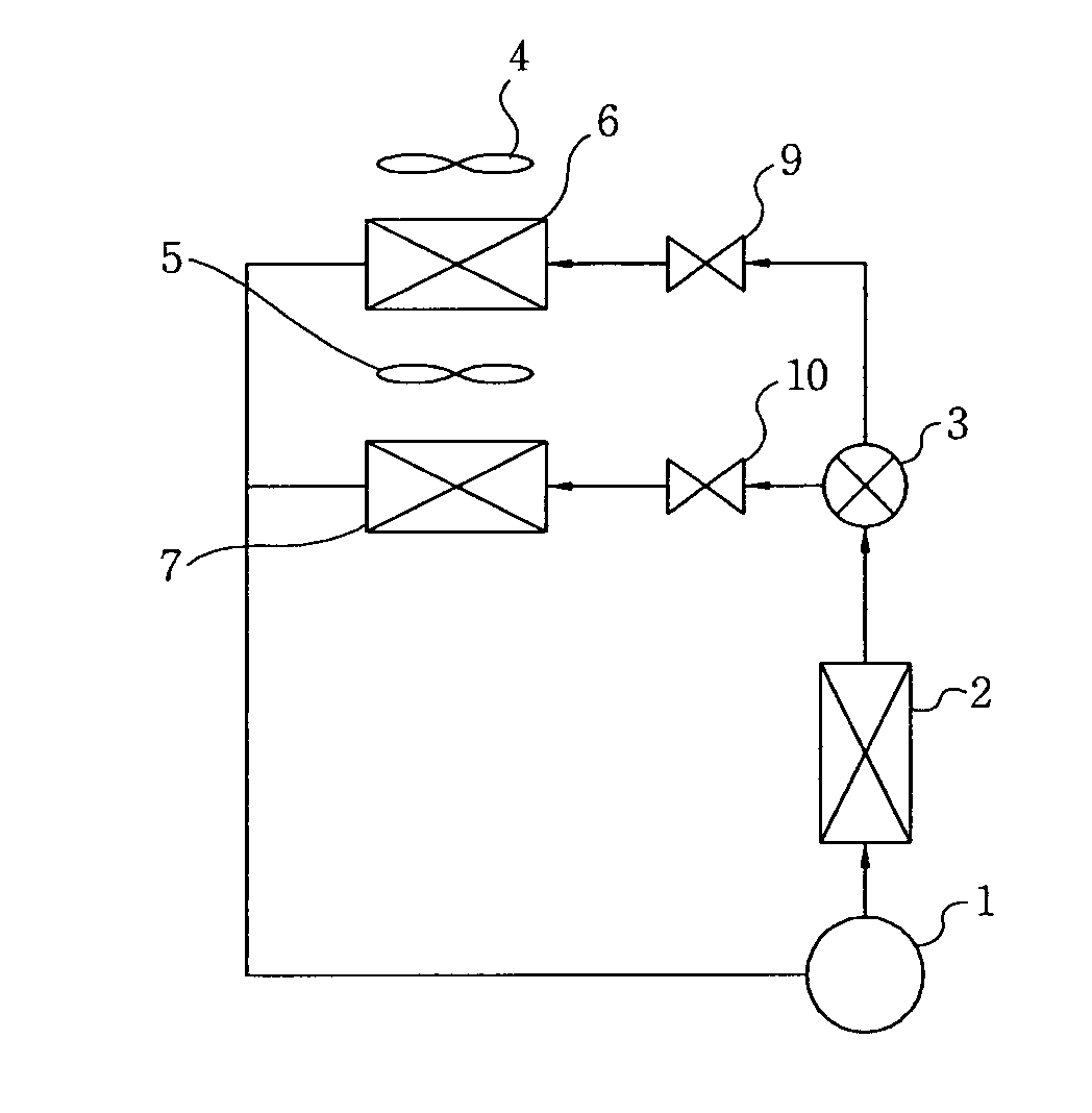
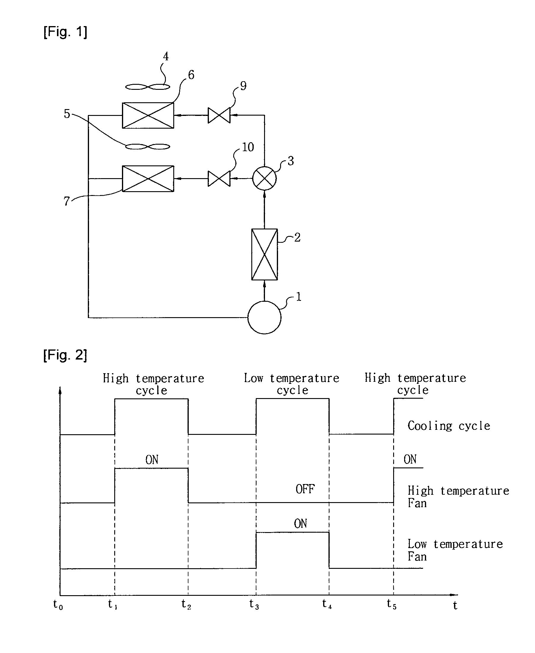
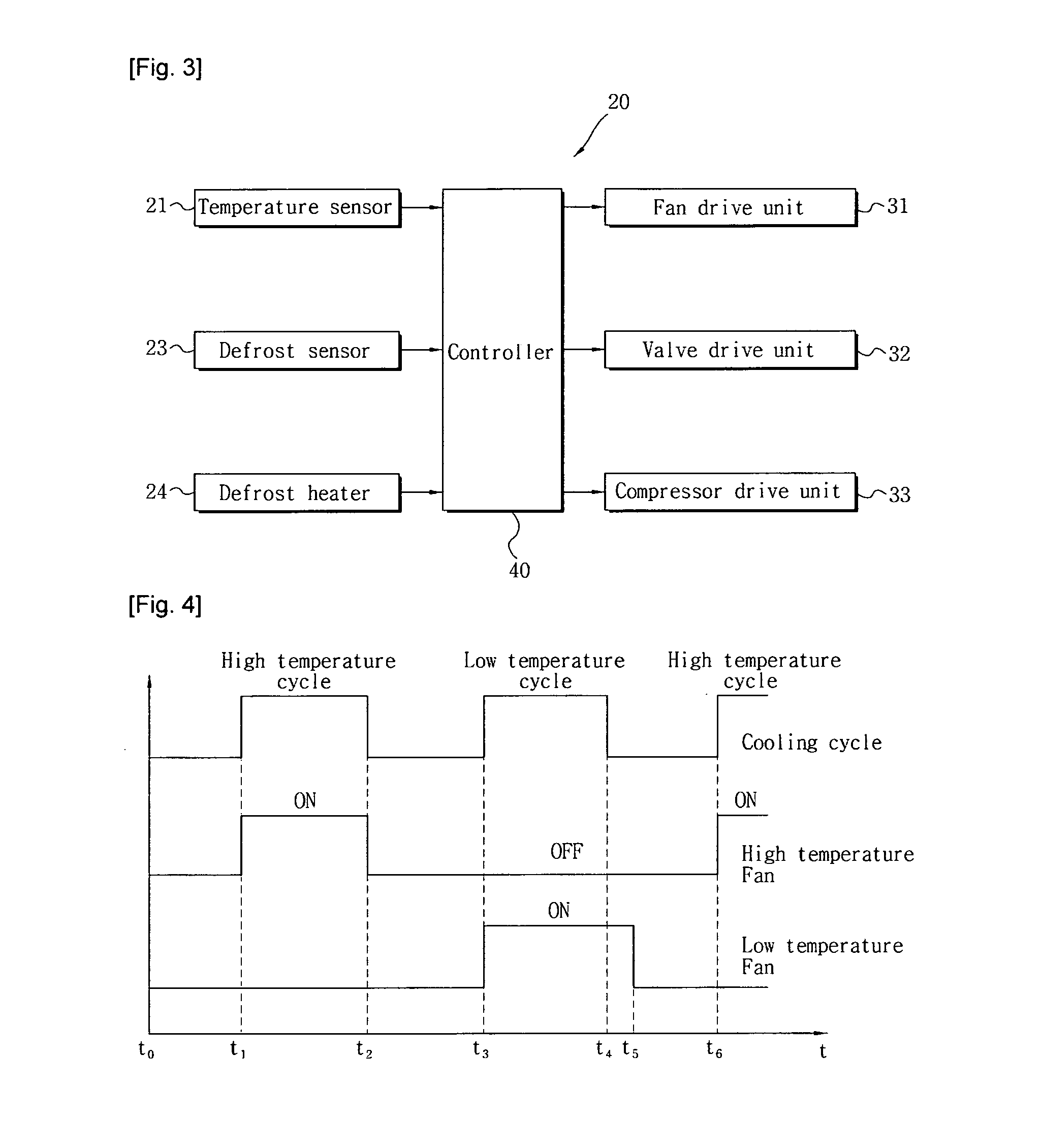
[0022]FIG. 3 is a schematic view for explaining a control method of a refrigerator according to the present invention. Referring to FIG. 1 and FIG. 3, a refrigerator 20 includes temperature sensors 21 for measuring the temperature of a high temperature evaporator 6, the temperature of a low temperature evaporator 7, and the interior temperatures of high temperature storage compartment and low temperature storage compartment, a defrost sensor 23 for sensing whether the high temperature evaporator 6 and the low temperature evaporator 7 have been frosted, a defrost heater 24 for applying heat to defrost the evaporators 6 and 7 if they have been frosted, a fan drive unit 31 for activating a high temperature fan 4 or a low temperature fan 5, a valve drive unit 32 for adjusting a valve 3 to direct refrigerants towards the high temperature evaporator 6, ...


PUM


Abstract

The present invention relates to a control method of a refrigerator which operates a cooling cycle including two storage compartments, a compressor, a condenser, a valve, fans, and evaporators for cooling the respective storage compartments, with one of the fans (5) corresponding to the storage compartment for storing items at relatively low temperatures being activated for a set amount of time even after the compressor is deactivated at the completion of cooling of the storage compartment for storing items at relatively low temperatures. In a refrigerator comprising a first storage compartment for storing an item, a second storage compartment for storing an item at a lower temperature than the first storage compartment, a cooling cycle including a compressor, a condenser for condensing a refrigerant from the compressor, a valve for directing the refrigerant from the condenser to first and second evaporators, with the first and second evaporators evaporating supplied refrigerants to cool the first and second storage compartments, respectively, and first and second (5) fans for circulating cool air from the first and second evaporators, respectively, and a controller for controlling the first and second (5) fans, the valve and the compressor, a control method of the refrigerator comprising: a first step of the controller activating the compressor if cooling of the second storage compartment is required and activating the second fan (5); and a second step of the controller deactivating the operation of the compressor, if the cooling of the second storage compartment is completed, and deactivating the operation of the second fan (5) after the operation of the compressor is deactivated.

Description

TECHNICAL FIELD[0001]The present invention relates in general to a control method of a refrigerator, and more particularly, to a control method of a refrigerator which operates a cooling cycle including two storage compartments, a compressor, a condenser, a valve, fans, and evaporators for cooling the respective storage compartments, with one of the fans corresponding to the storage compartment for storing items at relatively low temperatures being activated for a set amount of time even after the compressor is deactivated at the completion of cooling of the storage compartment for storing items at relatively low temperatures.BACKGROUND ART[0002]FIG. 1 is an explanatory view of a cooling cycle used in refrigerators according to the prior art. The cooling cycle includes a compressor 1, a condenser 2, a valve 3, fans 4 and 5, evaporators 6 and 7, a controller 8, and expansion means 9 and 10. The compressor 1 compresses refrigerants into high-temperature, high-pressure gaseous refriger...

Claims


Application Information

Patent Timeline
IPC IPC(8): F25D17/06F25D17/00F25D21/08
CPCF25B5/02F25B2600/0251F25B2600/112F25B2600/2511Y02B40/32F25D11/022F25D17/065F25D21/02F25D2600/02F25B2700/2117Y02B40/00F25D29/00
Inventor KIM, DONG-SEOKKANG, SUNG-HEESHIN, JONG-MINROH, CHULGIYOUN, DEOK-HYUN
Owner LG ELECTRONICS INC
Why Eureka
Try Eureka