Positive-displacement machine

a positive displacement and displacement technology, applied in the direction of positive displacement liquid engines, pump control, positive displacement engines, etc., can solve the problems of friction loss, cylinder-piston units of the second radial plane can be switched on or off, cylinder-piston units are always active, etc., to reduce the loss of machine energy, increase volumetric flow or torque, and increase idle volume

Inactive Publication Date: 2011-02-24
ROBERT BOSCH GMBH
View PDF3 Cites 51 Cited by
  • Summary
  • Abstract
  • Description
  • Claims
  • Application Information

AI Technical Summary

Benefits of technology

[0022]In an alternative refinement of the positive-displacement machine of the invention, the intermediate valves are proportional valves. Thus suction throttling can be achieved, as a result of which the secondary cylinders that are switched on are not completely filled. As a result, the volumetric flow or rpm stages that result from the stroke volumes of the secondary cylinder-piston units in a characteristic curve of the machine are smoothed.
[0023]If the cylinders of the secondary group are larger than the cylinders of the primary group, an increase in volumetric flow or tor

Problems solved by technology

A disadvantage of such hydrostatic positive-displacement machines is that all the cylinder-piston units are always active, or in other words that the volume flow of the machine is always defined by the displacement of all the units.
A disadvantage of such valve-controlled positive-displacement machines is

Method used


Image

  • Positive-displacement machine
  • Positive-displacement machine
  • Positive-displacement machine

Examples


Embodiment Construction

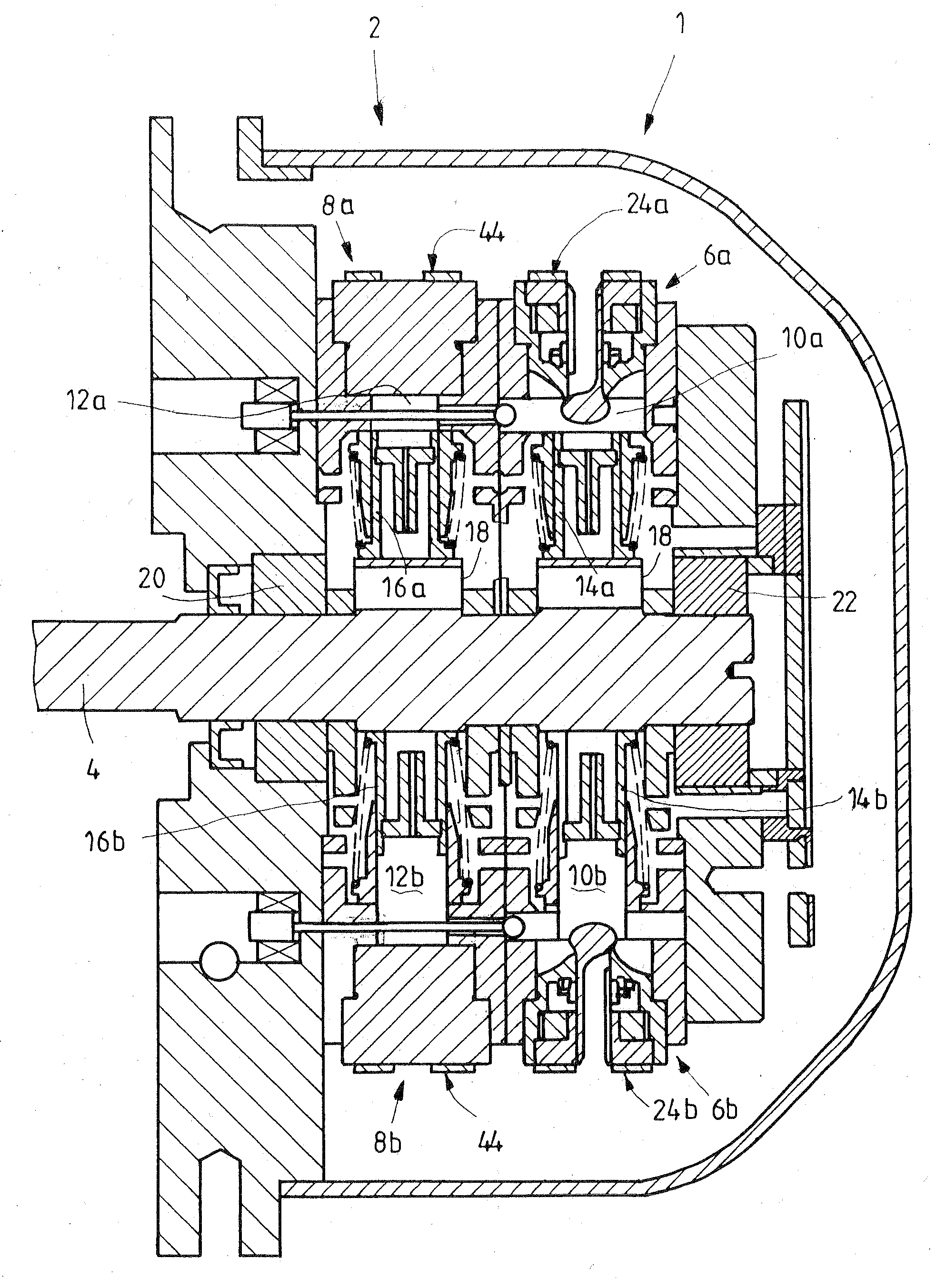
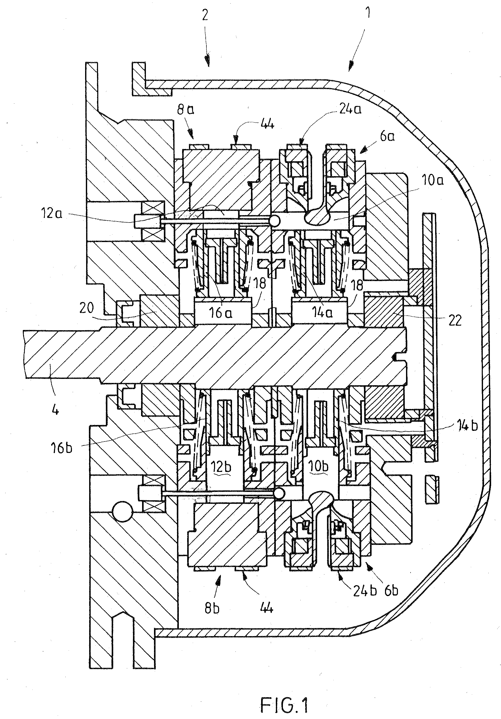
[0028]FIG. 1 shows an exemplary embodiment of a valve-controlled radial piston machine of the invention in section. It has a primary radial plane 1 and a secondary radial plane 2, and each plane 1, 2 has six cylinder-piston units, which are arranged in a star pattern around a shaft 4. Of the six units in each plane, only two units 6a, 6b and 8a, 8b, facing one another, are shown in FIG. 1. Each of the cylinder-piston units 6a, 6b, 8a, 8b has a work chamber 10a, 10b, 12a, 12b and a piston 14a, 14b, 16a, 16b; the pistons 14a, 14b, 16a, 16b are braced on an eccentric element 18 of the shaft 4.

[0029]The shaft 4, which depending on the mode of operation of the radial piston machine shown is a drive shaft or a power takeoff shaft, is supported rotatably, together with the eccentric element 18 secured to it, in the radial piston machine via two roller bearings 20, 22. FIG. 1 shows a rotary position of the eccentric element 18 in which a circumferential portion of comparatively large radius...


PUM


Abstract

A hydraulic positive-displacement machine includes at least two radially or axially spaced-apart groups of cylinder-piston units. The cylinders of the primary group can be made to communicate fluidically with cylinders of the secondary group via intermediate valves. At least two intermediate valves can be switched independently of one another.

Description

BACKGROUND OF THE INVENTION[0001]The invention relates to a hydraulic positive-displacement machine.[0002]In conventional hydrostatic positive-displacement machines, which can be embodied as radial or axial piston machines, for instance, the control of the inflow and outflow of the individual cylinder-piston units revolving along an orbit is done mechanically. In the case of an axial piston pump, for example, two pressure crescents are used, by way of which the connections with the high-pressure side and the low-pressure side open during a certain range of the orbit and thus during a certain stroke segment of the cylinder-piston units.[0003]In radial piston pumps, one high-pressure valve and one low-pressure valve per cylinder-piston unit are provided, and the valves are, mechanically controlled. The high-pressure valve of each unit for instance always opens if a certain built-up pressure in the applicable cylinder of the unit is exceeded, so that the pressure fluid with elevated pr...

Claims


Application Information

Patent Timeline
IPC IPC(8): F04B49/22F04B1/00
CPCF04B1/0404F04B49/22F04B1/063
Inventor DUERR, MICHAEL
Owner ROBERT BOSCH GMBH
Why Eureka
Try Eureka