Multiplexing Drive Circuit For An AC Ignition System

a technology of ac ignition system and multi-drive circuit, which is applied in the direction of machines/engines, mechanical equipment, lighting and heating apparatus, etc., can solve the problems of limiting the amount of adjustability in ca and sd, unable to independently adjust parameters, and open circuit voltag

Active Publication Date: 2011-02-24
WOODWARD GOVERNOR CO
View PDF14 Cites 15 Cited by
  • Summary
  • Abstract
  • Description
  • Claims
  • Application Information

AI Technical Summary

Benefits of technology

[0008]In one aspect, an embodiment of the invention provides a multiplexing drive circuit for an AC ignition system having a common leg that includes two switches coupled in series, and one or more dedicated legs, wherein each dedicated leg includes two switches coupled in series. The AC ignition system also includes a transformer (with two-winding ignition coil) for each of the one or more dedicated legs, each transformer having a primary winding coupled between one of the one or more dedicated legs and the common leg. Furthermore, each transformer has a secondary winding coupled in parallel to a spark plug. The AC ignition system also includes a pulse-width modulated (PWM) switch controller configured to operate the common leg and dedicated leg switches to control characteristics of the spark discharge for the spark plug.

Problems solved by technology

However, once energy has been placed in the magnetic core, the secondary coil characteristics are for the most part predetermined to be whatever the secondary load allows and cannot be changed until the next firing.
The biggest constraint in these systems is open circuit voltage.
This limits the amount of adjustability in CA and SD that is available through adjusting energy application.
In conventional inductive or capacitive discharge coil designs, these parameters cannot be adjusted independently.
And, typically, for a given coil design, the relationship between the OCV, CA, and SD cannot be optimized for different engine operating conditions.
Generally, as coil complexity decreases, the use of power semiconductors increases and vice versa.
This makes AC ignition systems more costly to build and potentially less reliable as the additional components and increased complexity provide more points of possible failure.
Further, many AC ignition systems do not permit precise real-time control of the secondary coil current, which determines the characteristics of the spark discharge.

Method used


Image

  • Multiplexing Drive Circuit For An AC Ignition System
  • Multiplexing Drive Circuit For An AC Ignition System
  • Multiplexing Drive Circuit For An AC Ignition System

Examples


Embodiment Construction

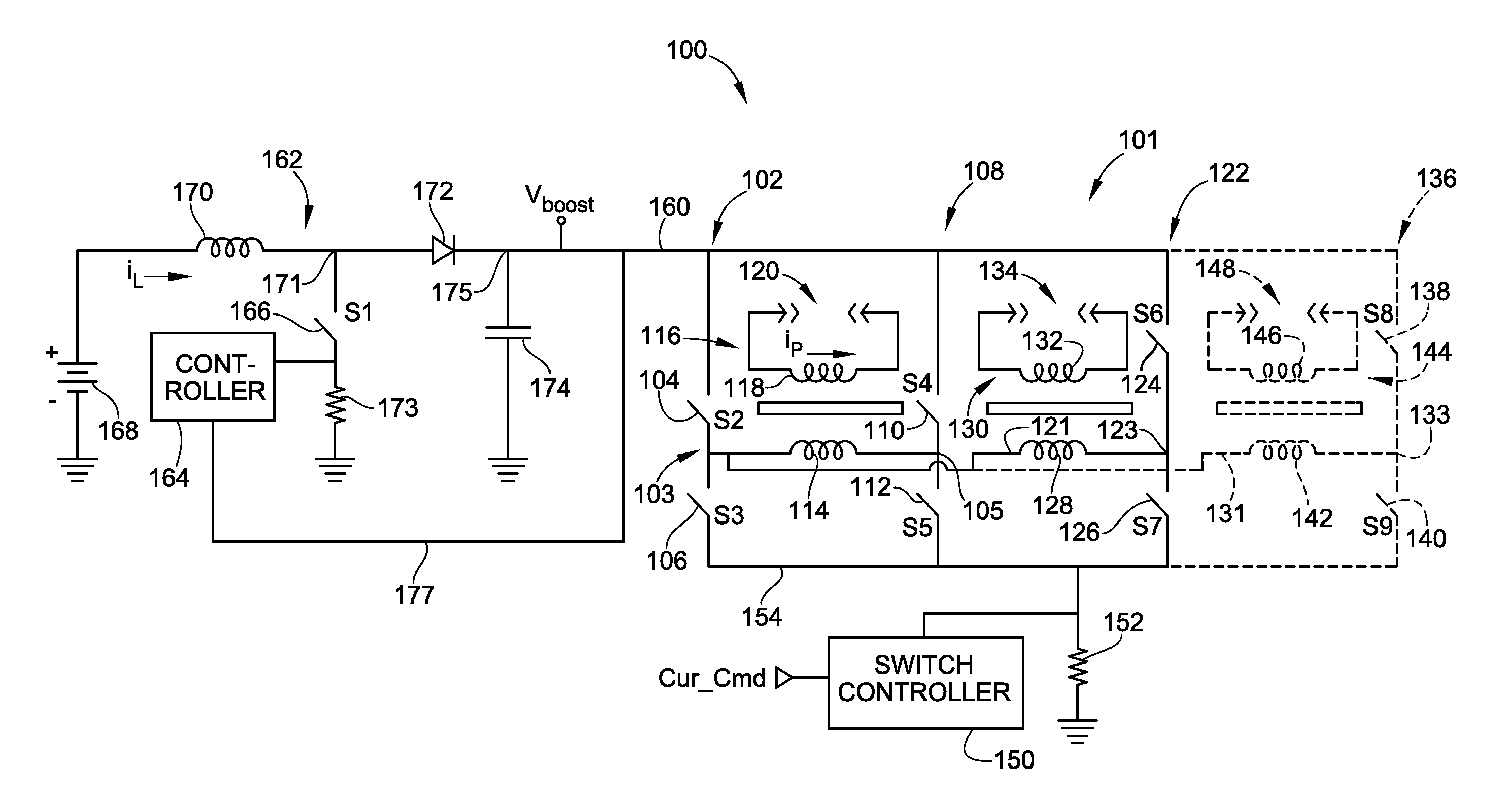
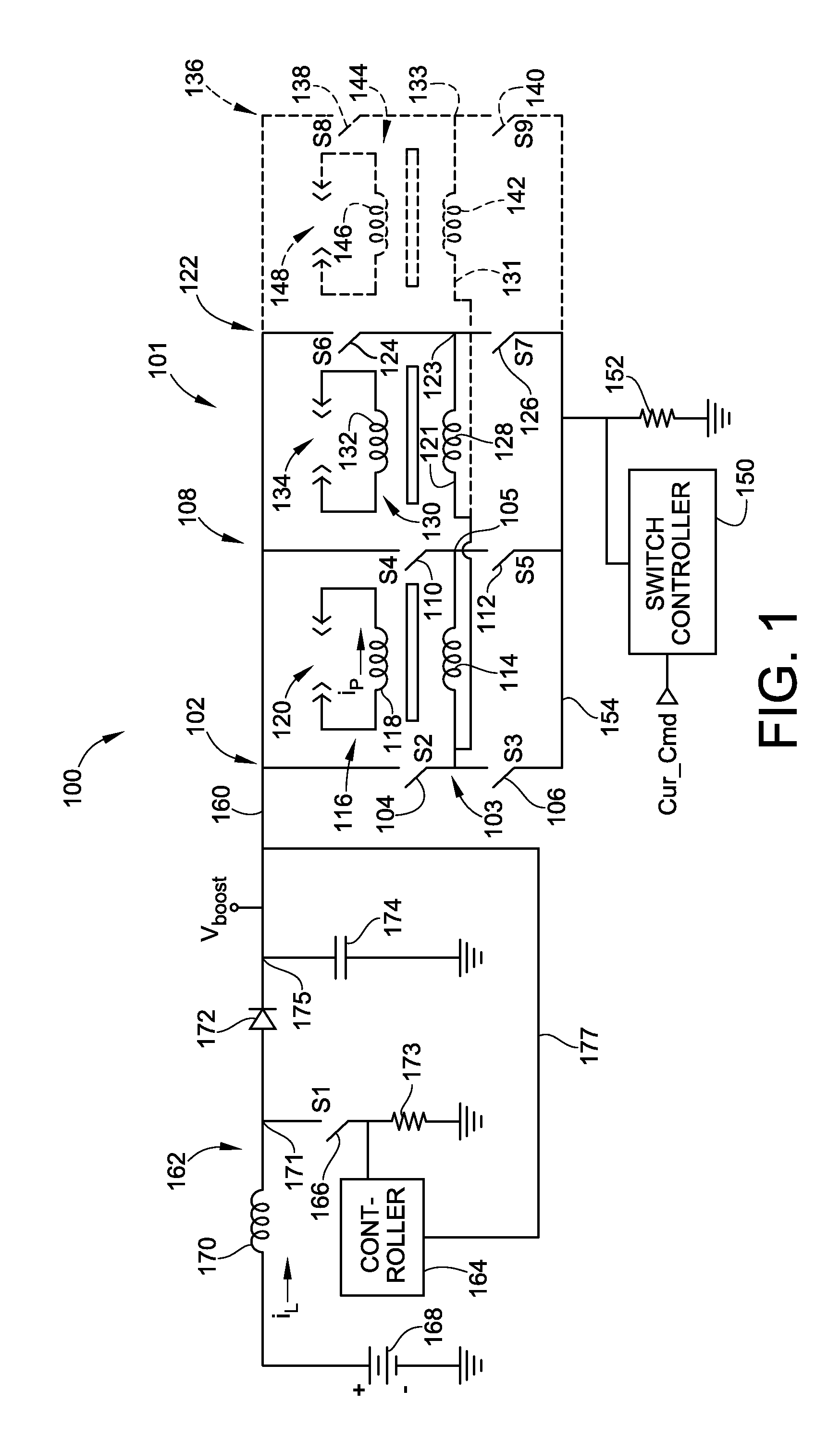
[0016]FIG. 1 illustrates an exemplary alternating current (AC) ignition system module 100 having a multiplexing drive circuit 101, according to an embodiment of the invention. Ignition system module 100 can be configured as a 3-channel, that is, coupled to three spark plugs, or a two-channel module, that is, coupled to two spark plugs, and includes a shared, or common, leg 102 having two switches S2, 104 and S3, 106 coupled in series. A first dedicated leg 108 has two switches S4, 110 and S5, 112 coupled in series. One terminal 103 of a primary winding 114 of a first ignition coil or transformer 116 is coupled between switches S2, 104 and S3, 106, while the other terminal 105 of the primary winding 114 is coupled between switches S4, 110 and S5, 112. A secondary winding 118 of the first transformer 116 is coupled in parallel with a first spark plug 120. Because the ignition coils in the present invention do not have to store as much energy as ignition coils in prior art ignition sys...


PUM


Abstract

A multiplexing drive circuit for an AC ignition system having a common leg that includes two switches coupled in series, and one or more dedicated legs, wherein each leg includes two switches coupled in series. The multiplexing drive circuit also includes a transformer for each of the one or more dedicated legs, each transformer having a primary winding coupled between one of the one or more dedicated legs and the common leg, and wherein each transformer has a secondary winding coupled in parallel to a spark plug, and a pulse-width modulated (PWM) switch controller configured to operate the common leg and dedicated leg switches to control characteristics of the spark discharge for the spark plug.

Description

FIELD OF THE INVENTION[0001]This invention relates generally to ignition systems for internal combustion engines and, more particularly, to ignition systems for internal combustion engines that use spark plugs.BACKGROUND OF THE INVENTION[0002]Typically, internal combustion engines include spark plugs along with spark-generating ignition circuitry to ignite an air-fuel mixture in the cylinder of the engine. Some engines employ permanent magnets attached to a rotating flywheel to generate a voltage on a charge coil. In a typical capacitive discharge system, electrical energy from a low voltage battery is fed into a power supply that steps it up to a higher voltage on a capacitor, which provides the voltage necessary to cause an electrical spark across the spark gap of a spark plug. The capacitor transfers its energy into the primary winding of an ignition coil and into the magnetic core of the ignition coil. Energy is extracted from the ignition coil secondary winding until the capaci...

Claims


Application Information

Patent Timeline
Patent Type & Authority Applications(United States)
IPC IPC(8): F02P5/00F23Q3/00
CPCF02P15/02F02P3/01
Inventor PETRUSKA, DAVID C.
Owner WOODWARD GOVERNOR CO
Why Eureka
Try Eureka