Plasma etching device

a technology of etching device and plasma, which is applied in the direction of electrical equipment, basic electric elements, electric discharge tubes, etc., can solve the problems of irregular flickering of plasma between the vents, uniform exhaustion of reaction gas, and failure to secure the plasma uniformity within the chamber, so as to improve the uniformity of plasma

Inactive Publication Date: 2011-02-24
DMS CO LTD
View PDF3 Cites 31 Cited by
  • Summary
  • Abstract
  • Description
  • Claims
  • Application Information

AI Technical Summary

Benefits of technology

[0015]An aspect of exemplary embodiments of the present invention is to address at least the problems and/or disadvantages and to provide at least the advantages described below. Accordingly, an aspect of exemplary embodiments of the present invention is to maintain a uniformit

Problems solved by technology

Firstly, because the reaction gas, the polymer, or the particle generated after plasma reaction is pump exhausted through one baffle plate, there is a limit in uniformly exhausting the reaction gas, the by-product, etc. Thus, there is a problem that it fails to secure the plasma uniformity within the chamber.
Secondly, because the baffle plate is not effectively grounded to the chambe

Method used


Image

  • Plasma etching device
  • Plasma etching device
  • Plasma etching device

Examples


Embodiment Construction

[0033]Exemplary embodiments of the present invention will now be described in detail with reference to the annexed drawings. In the following description, a detailed description of known functions and configurations incorporated herein has been omitted for conciseness.

[0034]A description of the present invention is made in detail with reference to the accompanying drawings.

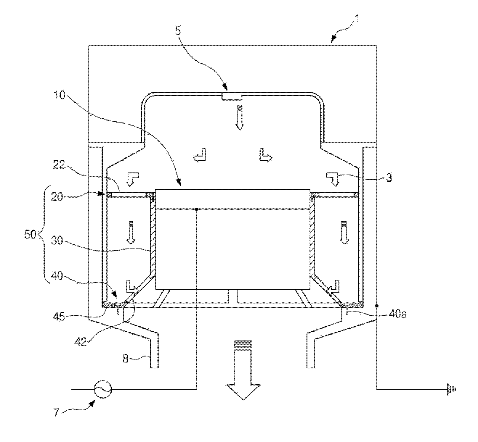
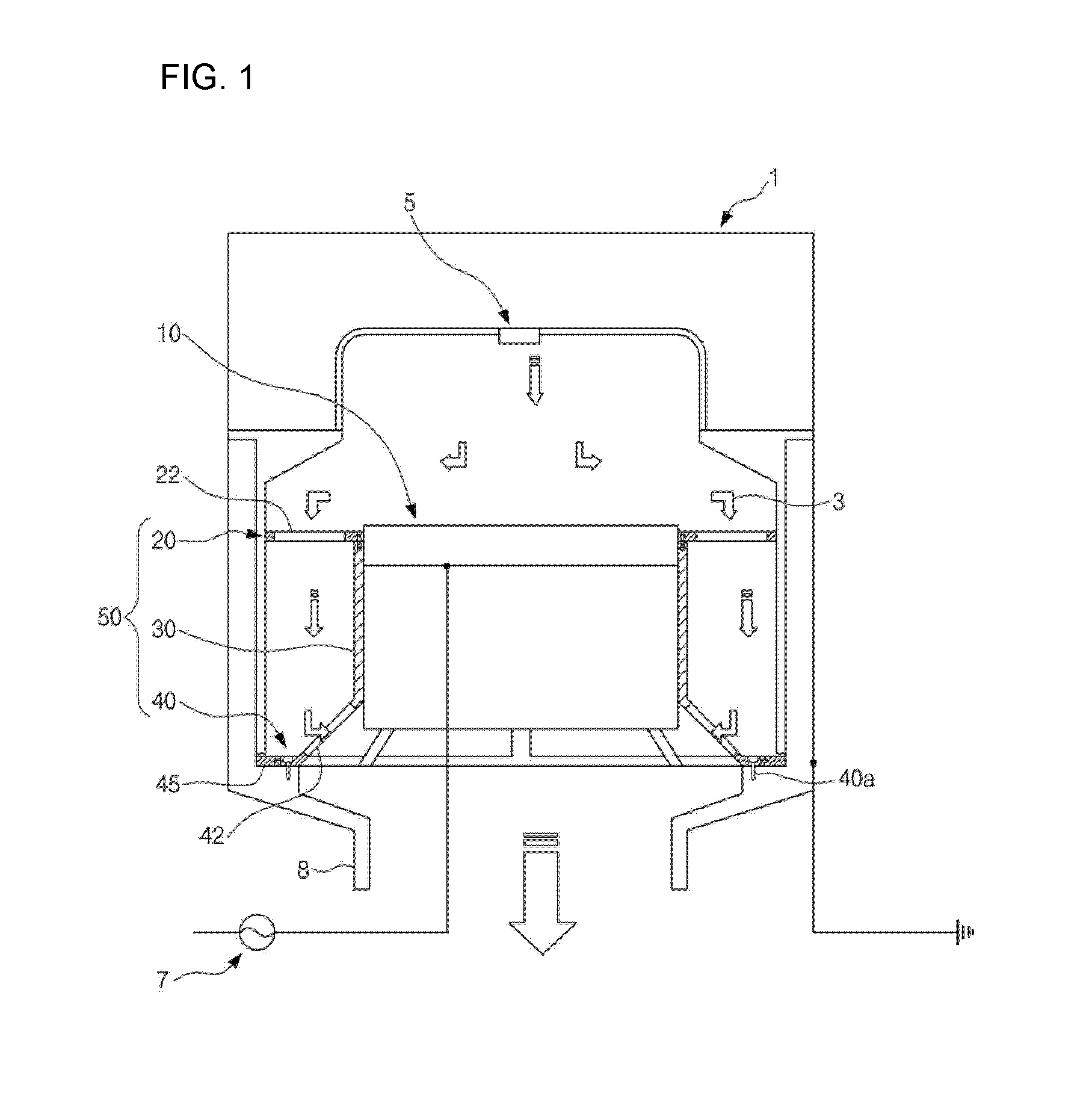
[0035]FIG. 1 is a schematic side diagram illustrating a plasma etching device according to the present invention.

[0036]As illustrated in FIG. 1, the plasma etching device of the present invention includes a chamber 1, a cathode assembly 10, and a cathode liner 50.

[0037]The chamber 1 is to provide a plasma reaction space isolated from the external. A gas injector 5 jetting a reaction gas is installed at a top and center of the chamber 1. An exhaust port 8 is formed at a bottom and center of the chamber 1 to discharge a reaction by-product such as a reaction gas, a polymer, a particle, etc. to the external.

[0038]Als...


PUM

PropertyMeasurementUnit
Lengthaaaaaaaaaa
Angleaaaaaaaaaa
Ratioaaaaaaaaaa

Abstract

A plasma etching device is provided. The device includes a chamber, a cathode assembly, and an integral cathode liner. The chamber provides a plasma reaction space. The cathode assembly is positioned at an inner and central part of the chamber and supports a substrate. The integral cathode liner has a plurality of first vents and second vents formed at two levels and spaced apart respectively such that the uniformity of a gas flow and exhaust flow within the chamber is maintained, and is outer inserted to the cathode assembly and coupled at its lower end part to an inner surface of the chamber.

Description

CROSS REFERENCE[0001]This application claims foreign priority under Paris Convention and 35 U.S.C. §119 to Korean Patent Application No. 10-2009-0076043, filed Aug. 18, 2009 with the Korean Intellectual Property Office.BACKGROUND OF THE INVENTION[0002]1. Technical Field[0003]The present invention relates to a plasma etching device for treating a large size wafer. More particularly, the present invention relates to a plasma etching device for improving plasma uniformity by outer inserting an integral cathode liner having a plurality of first vents and second vents formed at two levels respectively to be spaced apart, to a cathode assembly such that the uniformity of a gas flow and exhaust flow of a reaction gas within a chamber is maintained and simultaneously, preventing a flickering phenomenon by grounding a lower end part of the integral cathode liner to the chamber.[0004]2. Description of the Related Art[0005]Generally, a large size wafer used for a semiconductor integrated circu...

Claims


Application Information

Patent Timeline
IPC IPC(8): C23F1/08
CPCH01J37/3244H01J37/32449H01J37/32834H01J37/32633H01J37/32623H01L21/3065
Inventor LEE, DONGSEOKCHAE, HWANKOOKMOON, HEESEOKCHOI, YUNKWANG
Owner DMS CO LTD
Why Eureka
Try Eureka