Magnet interrupter for high voltage switching

a technology of high-voltage switching and magnet interrupter, which is applied in the direction of high-tension/heavy-dress switches, air-break switches, electrical apparatus, etc., can solve the problems of increasing cost, reducing reliability, and affecting the reliability of high-voltage switches, so as to reduce operating costs, less robust parts, and easy to adapt to transmission voltage levels

Active Publication Date: 2011-02-24
SOUTHERN STATES
View PDF4 Cites 18 Cited by
  • Summary
  • Abstract
  • Description
  • Claims
  • Application Information

AI Technical Summary

Benefits of technology

[0009]The present invention meets the needs described above in a magnetic circuit interrupter using ring type magnets to rotate the arcing current in a radial plane perpendicular to the axial direction of gap opening. Permanent magnets may be used to spin the arc so that the magnetic field is not affected by the magnitude of the arcing current, which makes the magnetic interrupter suitable for interrupting currents below fault level currents, such as switching line, loop, and load currents on high voltage transmission lines. Testing has shown that this configuration is more successful than cylindrical magnets embedded in the center of the contacts and spaced apart across the arc gap. The ac

Problems solved by technology

Circuit breakers, which are used to interrupt much higher fault currents, are typically more expensive and designed to operate much less frequently.
Multiple bottles in series are required for higher voltages which increases cost and decreases reliability.
Because of the increased cost and complex of multi-bottle configurations, linkages are used in order to share a single unit for two and three way switches.
Multiple vacuum bottles in series are required to reach transmission voltage ratings increasing the complexity and cost.
This can also be a hazard to operating personnel.
In general, these config

Method used


Image

  • Magnet interrupter for high voltage switching
  • Magnet interrupter for high voltage switching
  • Magnet interrupter for high voltage switching

Examples


Embodiment Construction

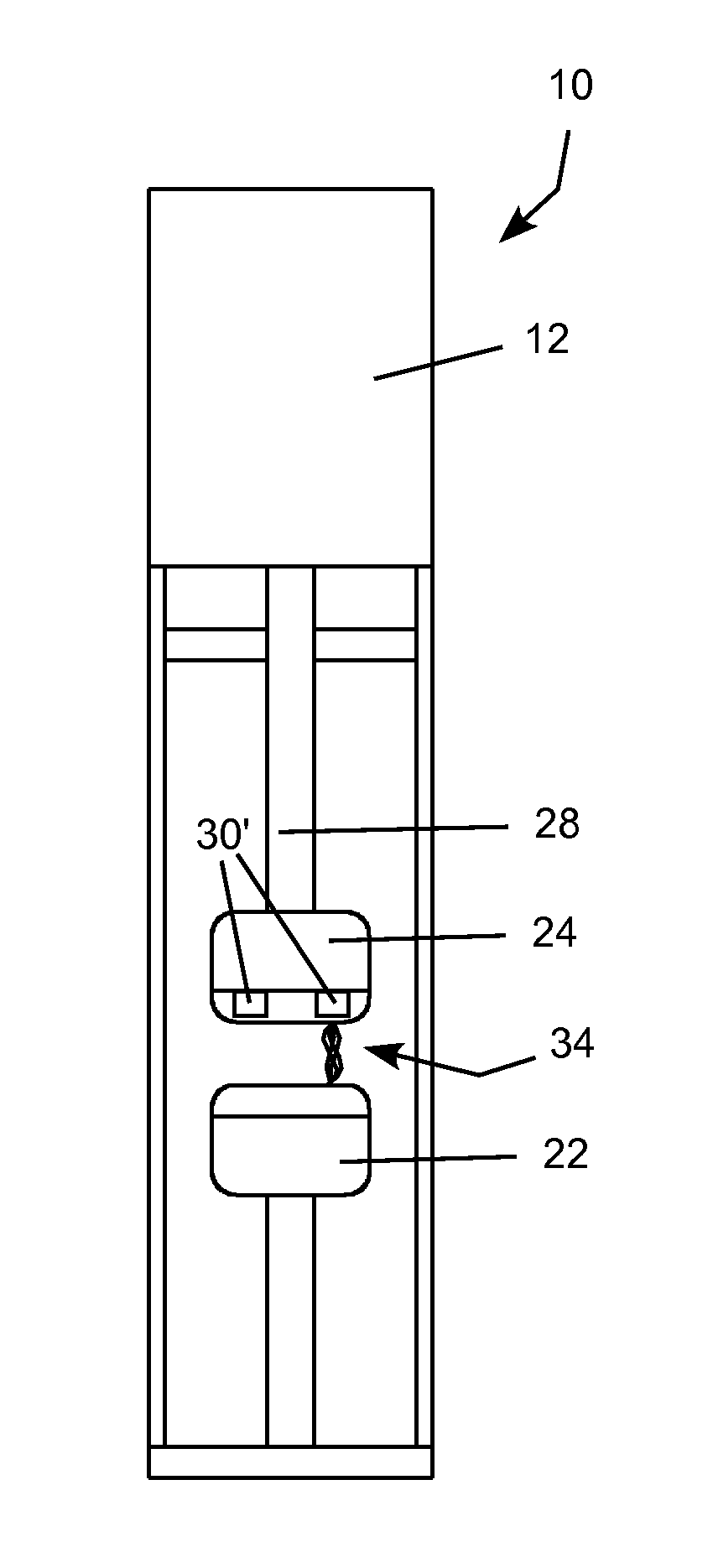
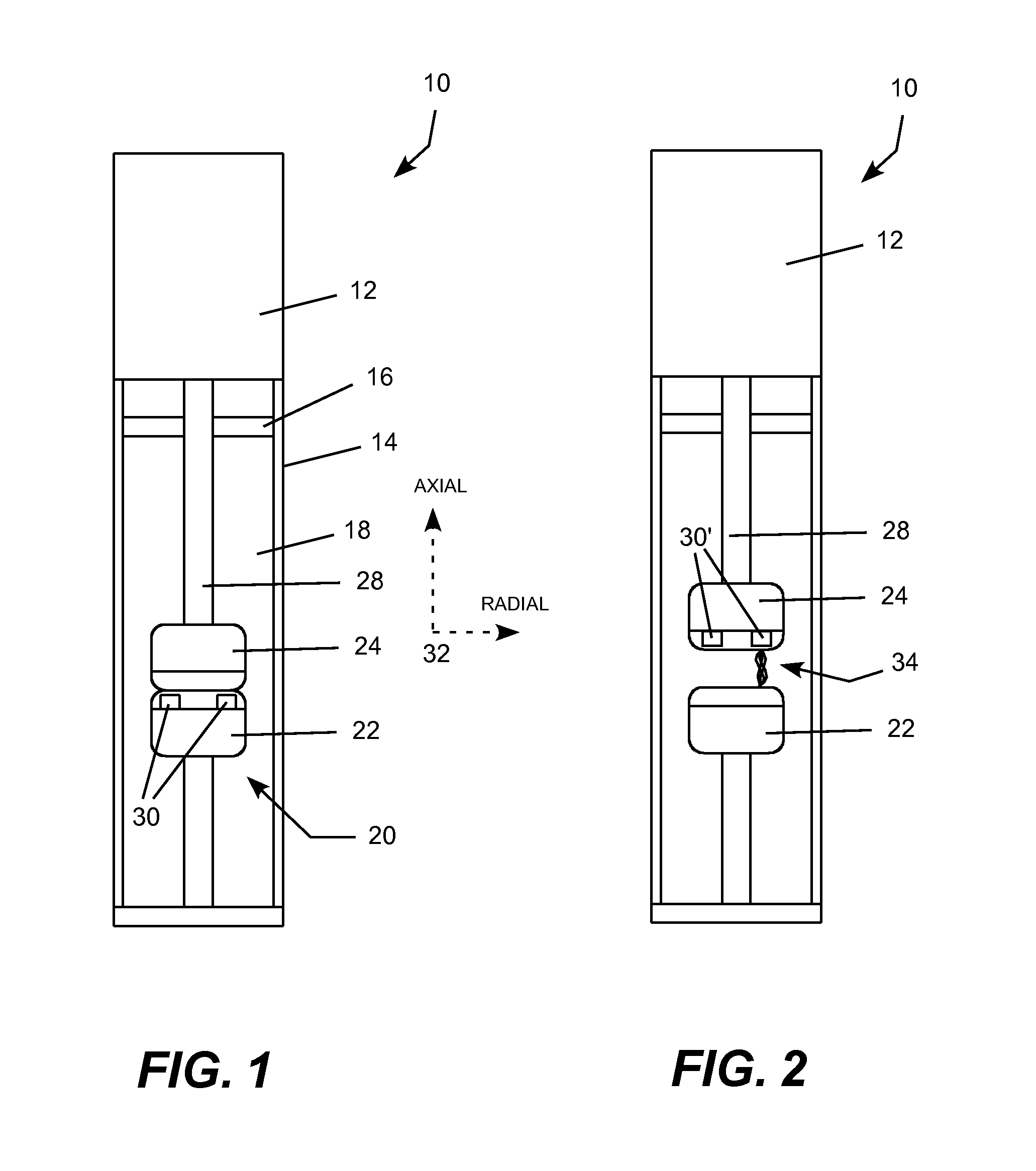
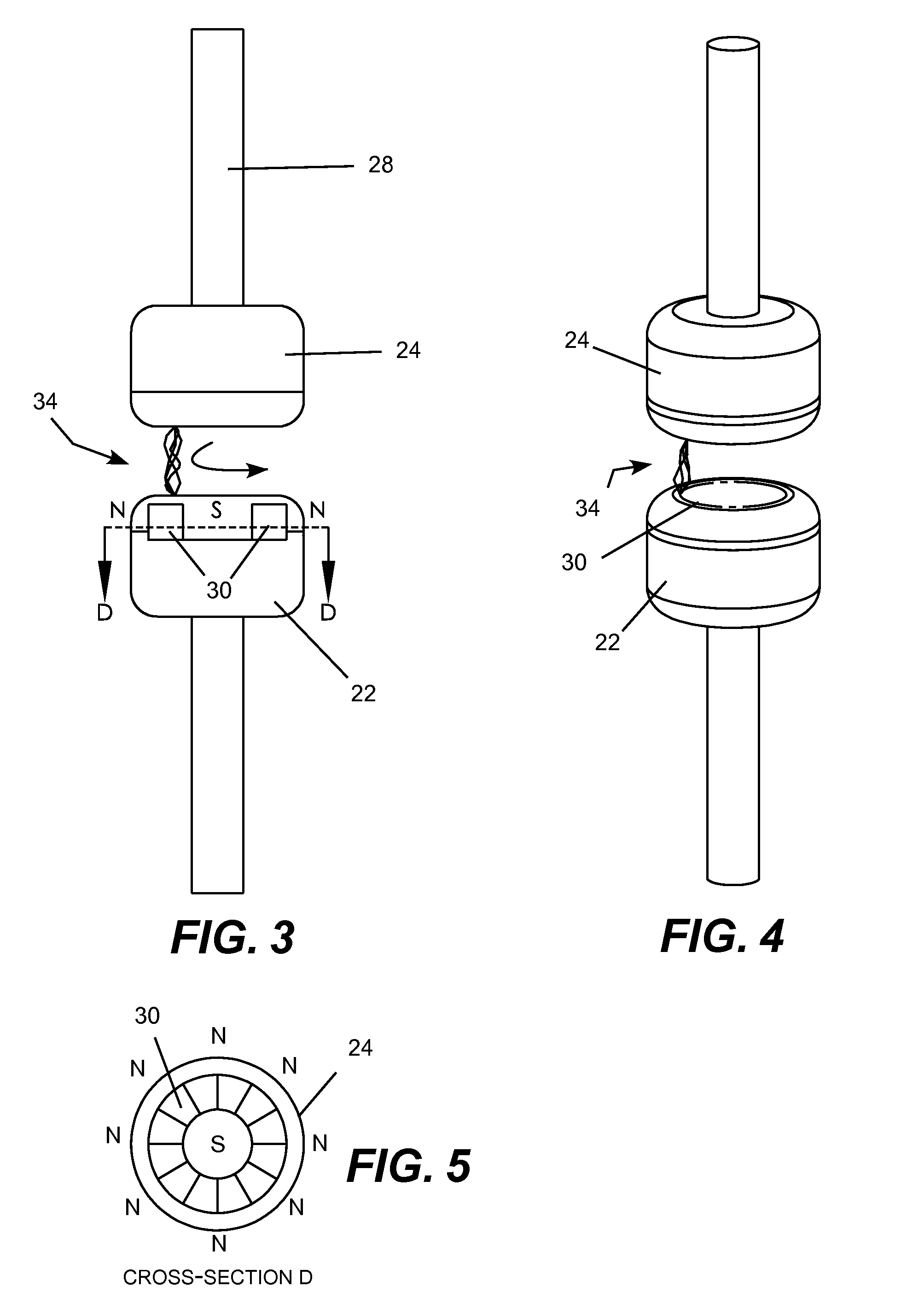
[0029]The present invention may be embodied in a magnetic interrupter consisting of a stationary and moving butt contacts that open an electric circuit in dielectric gas (e.g., SF6) contained in a sealed, pressurized insulating housing. One or both of the contacts contain a magnet with poles spaced apart in a radial plane perpendicular to the axial direction to spin the arc in the radial plane about the center of the contacts. The invention is well suited for arc extinguishing in interrupting disconnect switches rated 72.5 kV and above. The moving contact is connected to a drive mechanism or actuator, such as an over toggle linkage system that locks the contacts in the closed position. When an external lever is moved the linkage collapses and springs move the contact to the open position. A torsion spring returns the external lever to the original position and the contacts close. The arc generated when the contacts open is completely contained in the housing. Vacuum bottles and puff...


PUM


Abstract

A magnetic interrupter consisting of a stationary and moving butt contacts that open an electric circuit in dielectric gas (e.g., SF6) contained in a sealed, pressurized insulating housing. One or both of the contacts contain a magnet with poles spaced apart in a radial plane perpendicular to the axial direction to spin the arc in the radial plane about the center of the contacts. Permanent magnets may be used to spin the arc so that the magnetic field is not affected by the magnitude of the arcing current, which makes the magnetic interrupter suitable for interrupting currents below fault level currents. One or both of the magnets may also be a field coil and a permanent magnet may be used in combination with a field coil.

Description

REFERENCE TO PRIORITY APPLICATIONS[0001]This application claims priority to commonly-owned U.S. Provisional Patent Application No. 61 / 235,089, which is incorporated herein by reference.REFERENCE TO DISCLOSURES INCORPORATED BY REFERENCE[0002]This application incorporates by reference the disclosures of commonly-owned U.S. Pat. Nos. 7,115,828; 7,078,643; 6,583,978; 6,483,679; 6,316,742 and 6,236,010, which are incorporated herein by reference.TECHNICAL FIELD[0003]The present invention relates to electric switchgear and, more particularly, relates to a high voltage electric power switch employing one or more ring shaped permanent magnets to spin the arc that develops within a contact gap.BACKGROUND OF THE INVENTION[0004]High voltage disconnect switches and circuit interrupters are used for a variety of purposes, such as interrupting line, loop, and load currents and switching reactors, capacitors and other circuit devices. Different types of switches are designed to meet different need...

Claims


Application Information

Patent Timeline
IPC IPC(8): H01H33/18
CPCH01H33/56H01H33/182
Inventor BLALOCK, FRANK CLAYROSTRON, JOSEPH R.STONE, JEREMY ANDREW
Owner SOUTHERN STATES
Why Eureka
Try Eureka