Fluid-filled vibration damping device and control method of the device used as engine mount

a technology of vibration damping device and fluid chamber, which is applied in the direction of shock absorbers, machine supports, mechanical equipment, etc., can solve the problems of reducing vibration damping capabilities, complicated construction, and difficulty in achieving effective vibration damping of input vibration of a frequency range which falls outside the tuning frequency range, so as to avoid the loss of fluid tightness of the fluid chamber, the effect of effective vibration damping

Active Publication Date: 2011-02-24
SUMITOMO RIKO CO LTD
View PDF26 Cites 30 Cited by
  • Summary
  • Abstract
  • Description
  • Claims
  • Application Information

AI Technical Summary

Benefits of technology

[0083]The present invention affords the advantages of effective vibration damping of vibration over a wider frequency range by varying the tuning frequency of the orifice passages, as well as of avoiding loss of fluidtightness of the fluid chamber resulting from provision of a mechanism for resetting the tuning frequency of the orifice passages.

Problems solved by technology

A problem with fluid-filled vibration damping devices, however, is that while vibration damping is excellent with respect to vibration of a frequency range to which the orifice passage has been tuned beforehand, it is more difficult to achieve effective vibration damping of input vibration of a frequency range which falls outside of the tuning frequency range.
Particularly when the input vibration has a higher frequency than the tuning frequency, the orifice passage will become substantially obstructed due to antiresonance action, posing a risk that vibration damping capabilities will be diminished owing to a sharp rise in dynamic spring action constant.
Such a placement structure for the actuator shaft will entail problems such as difficulty in ensuring sealing of the wall of the fluid chamber in the section thereof penetrated by the rotary actuator shaft; complicated construction; and less reliable seals or lower durability of the mount itself.
Moreover, the procedure for sealing non-compressible fluid in the fluid chamber tends to be difficult, leaving numerous issues that must be resolved before such a design could be practical.

Method used


Image

  • Fluid-filled vibration damping device and control method of the device used as engine mount
  • Fluid-filled vibration damping device and control method of the device used as engine mount
  • Fluid-filled vibration damping device and control method of the device used as engine mount

Examples


first embodiment

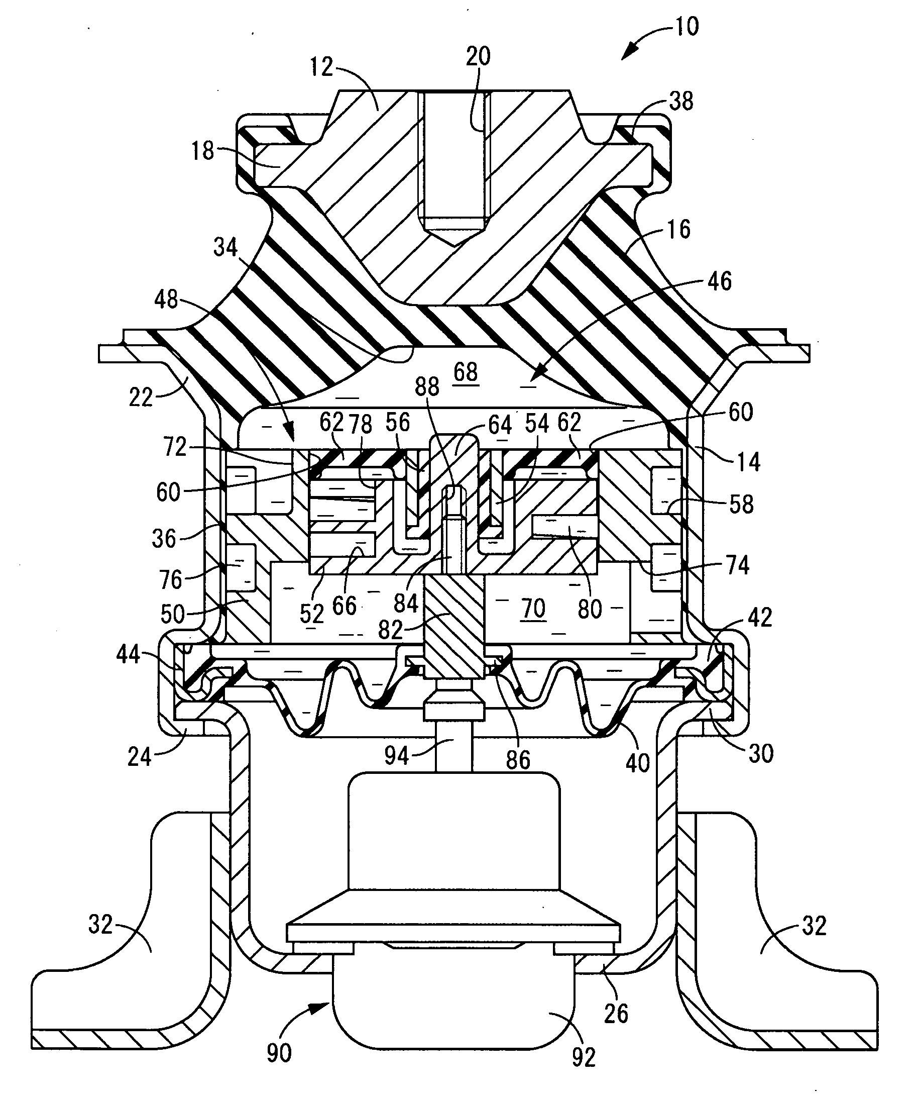
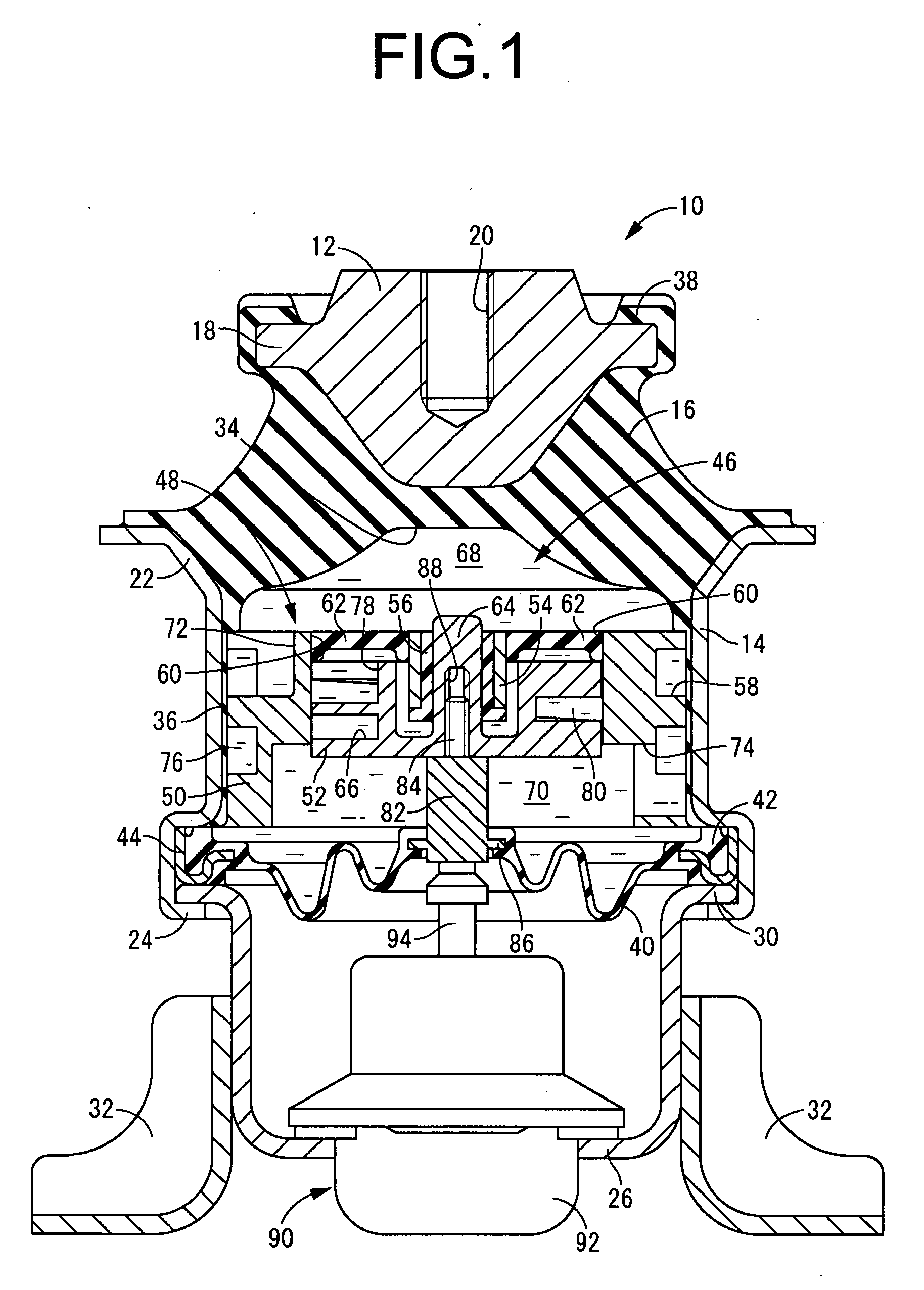
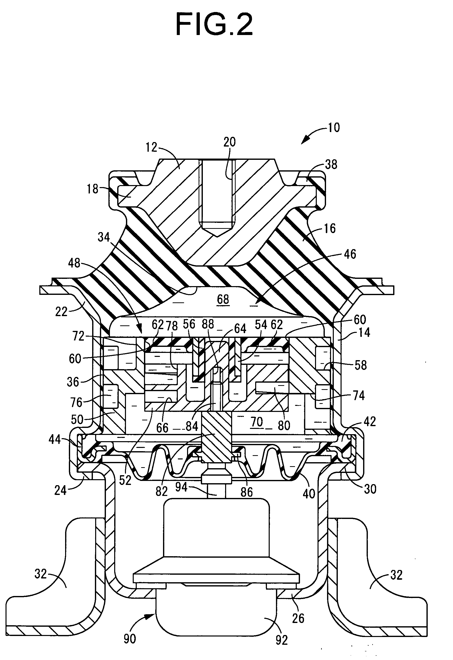
[0145]First, FIGS. 1 to 3 depict an automotive engine mount 10 as a fluid-filled vibration damping device constructed in accordance with the present invention. The engine mount 10 has a construction in which a first mounting fitting 12 provided as a first mounting member and a second mounting fitting 14 provided as a second mounting member are linked to one another by a main rubber elastic body 16. The first mounting fitting 12 is mounted onto the power unit (not shown) side, while the second mounting fitting 14 is mounted onto the vehicle body (not shown) side, so that the engine mount 10 provides vibration damping linkage between the power unit and the vehicle body.

[0146]To describe in greater detail, the first mounting fitting 12 has a small-diameter, approximately circular block shape, the upper part of which has tapered contours of gradually decreasing diameter towards the top in the axial direction, and the lower part of which has tapered contours of gradually decreasing diame...

third embodiment

[0201]Next, FIG. 7 depicts an automotive engine mount 100 according to the fluid-filled vibration damping device constructed according to the present invention. This engine mount 100 is furnished with a partition member 102.

[0202]Turning to a more detailed description, the partition member 102 has a thick, approximately circular disk shape on the whole, and includes a first orifice-defining member 104 provided as an outer orifice member, a second orifice-defining member 106 provided as an inner orifice member fitting inside the first orifice-defining member 104, and a cover fitting 108 superposed against the first orifice-defining member 104.

[0203]The first orifice-defining member 104 has a thick-walled, large-diameter, approximately round tubular shape of greater thickness in its axial upper side located to one side of a step formed on the inside peripheral face thereof, as compared to its lower side. That is, the first orifice-defining member 104 in the present embodiment has a st...

fourth embodiment

[0209]Next, FIG. 8 depicts an automotive engine mount 112 according to the fluid-filled vibration damping device constructed according to the present invention. This engine mount 112 has a partition member 114; the partition member 114 includes a first orifice-defining member 116 provided as an outer orifice member, and a second orifice-defining member 118 provided as an inner orifice member.

[0210]The first orifice-defining member 116 is a thick, large-diameter approximately circular disk shape having a step on the inside peripheral face as well as a circumferential groove 58 formed opening onto the outside peripheral face. This first orifice-defining member 116 fits into the inside peripheral side of the second mounting fitting 14 and is supported by the second mounting fitting 14.

[0211]Meanwhile, the second orifice-defining member 118 has a passage-defining member 120 of approximately round tubular shape with an orifice-defining groove 66 extending in the circumferential direction...


PUM


Abstract

A fluid-filled vibration damping device wherein a partition member is formed by fitting an inner orifice member inside an outer orifice member with the members relatively displaceable. An orifice-defining window is provided on either one of an inside peripheral face of the outer orifice member and an outside peripheral face of the inner orifice member. An orifice passage is defined utilizing a zone being produced through partial covering of the orifice-defining window by the other of the outer orifice member and the inner orifice member. The covered zone of the orifice-defining window changes through relative displacement of the inner orifice member and the outer orifice member, so that a passage length along the orifice passage changes in association with change of the covered zone of the orifice-defining window.

Description

TECHNICAL FIELD[0001]The present invention relates to a vibration damping device used as an automotive engine mount or the like. More particularly, the present invention relates to a fluid-filled vibration damping device that utilizes vibration damping based on flow action of a fluid filling the interior, and to an appropriate control method of the device used as an engine mount.BACKGROUND ART[0002]A number of vibration damping devices, which are designed for installation between components making up a vibration transmission system in order to provide vibration damped linkage and / or vibration damped support to these components, are known in the prior art. Such vibration damping devices have a construction in which a first mounting fitting adapted to mount onto one of the components making up a vibration transmission system and a second mounting fitting adapted to mount onto the other component are linked by a main rubber elastic body. With the goal of further enhancing vibration dam...

Claims


Application Information

Patent Timeline
Patent Type & Authority Applications(United States)
IPC IPC(8): F16F13/26F16F13/06
CPCF16F13/26
Inventor HASEGAWA, KOICHIYAMAMOTO, SEIICHIRO
Owner SUMITOMO RIKO CO LTD
Why Eureka
Try Eureka