Radiated power measurement method, radiated power measurement coupler and radiated power measurement apparatus

a technology of radiated power measurement and radiated power, which is applied in the direction of instruments, transmission monitoring, receiver monitoring, etc., can solve the problems of no test terminal, difficult spurious radiation measurement, and long measurement tim

Active Publication Date: 2011-02-24
ANRITSU CORP
View PDF3 Cites 22 Cited by
  • Summary
  • Abstract
  • Description
  • Claims
  • Application Information

AI Technical Summary

Benefits of technology

[0024]An object of the invention is to provide a radiated power measurement method, a radiated power measurement coupler and a radiated power measurement apparatus capable of measuring the total radiated power accurately free of the effects of the size or directivity of the DUT.
[0025]Incidentally, a concept or concepts of the invention is based on the knowledge that the coupling degree between the DUT and the receiving antenna is increased and a more desirable result can be obtained by measuring the whole power including the multiple reflection components radiated from the DUT. Specifically, the interior of the enclosed space of the ellipsoidal coupler is basically regarded free of loss, and therefore, as long as the input reflection coefficient of a radiator such as the DUT or a reference antenna replacing the DUT is sufficiently small, the entire power radiated from the particular radiator should be retrieved as a load on the receiving antenna. In other words, an ideal coupler having the coupling degree of unity should be able to be obtained. This fact is established regardless of the size or directivity of the radiator.

Problems solved by technology

Many of these devices, unlike the conventional radio communication devices, have no test terminal due to the dimensional limitation or the economic reason.
On the other hand, large equipment including a radio wave non-reflection chamber and a spherical surface scanner is required, and it takes a long time to measure.
Therefore, the receiving sensitivity at each measurement point is so small that the problem is posed that the measurement of spurious radiation is difficult.
It is very difficult to measure these spurious radiations by the measurement method described above.
The problems of this method, however, are that the coincidence between the artificially generated random field and the theoretical probability model remains ambiguous, the statistical process on which the method is based makes a large inaccurate result, the measurement requires a long time, and the like.
Another problem of this method is that, like in the spherical surface scanning method, the spurious radiation cannot be measured easily.
Also, the method using the G-TEM cell poses the problem that not only it is difficult to secure the uniformity of the internal field distribution but also the measurement of the total radiated power makes it necessary to arrange a two-axis rotary table in the G-TEM cell to make it possible to move the DUT in all directions.
This poses, therefore, the problem that not only the system is complicated and high in cost but also the DUT is limited to the dipole antenna.
Also, the measurement of the spurious radiation is difficult as in each of the aforementioned methods.
It has been found, however, in the case where the DUT is large in size and the beam radiated from the DUT is divided into a plurality of components or the radio wave output from the DUT has a side lobe, a cancellation phenomenon occurs in which the beams of different phases are concentrated in the neighborhood of the focal points to weaken the radio wave, thereby making it difficult to measure the total radiated power accurately.

Method used


Image

  • Radiated power measurement method, radiated power measurement coupler and radiated power measurement apparatus
  • Radiated power measurement method, radiated power measurement coupler and radiated power measurement apparatus
  • Radiated power measurement method, radiated power measurement coupler and radiated power measurement apparatus

Examples


first embodiment

(Radiated Power Measurement Method )

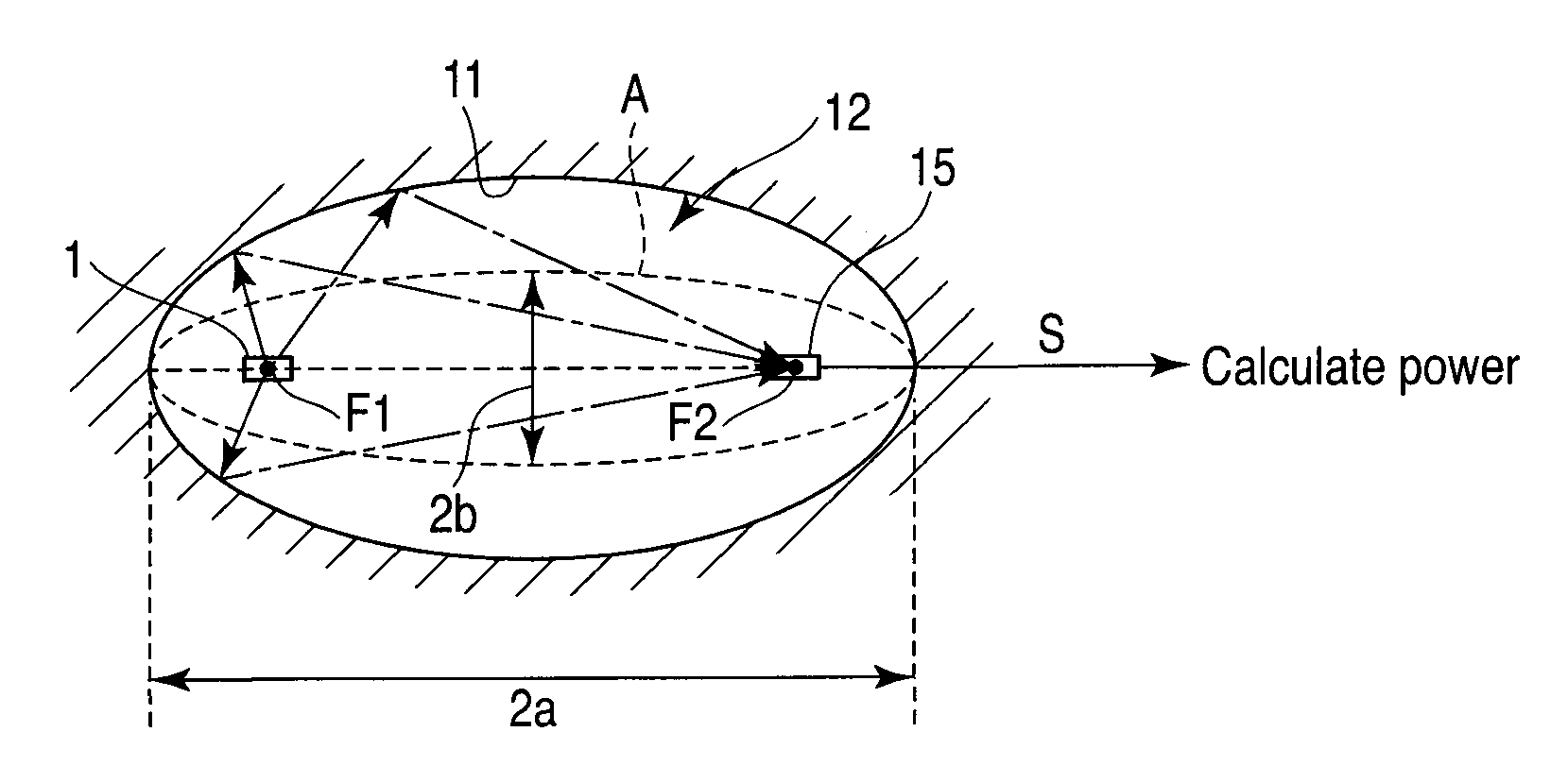
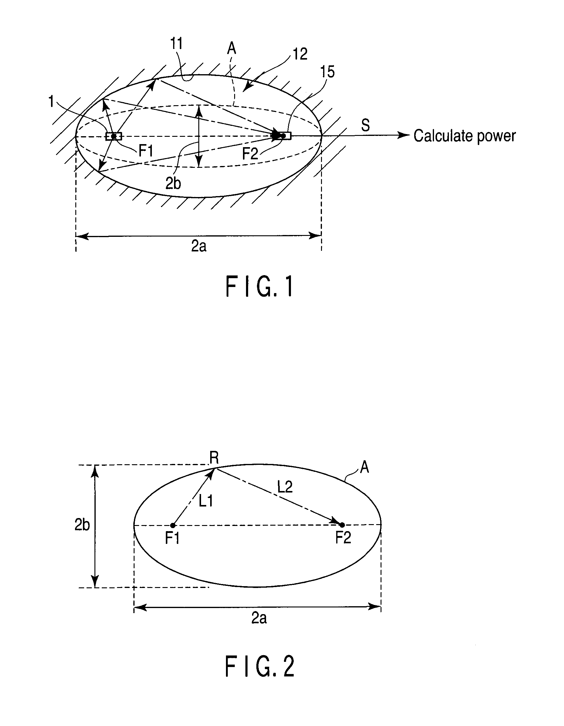
[0149]As understood from the foregoing description, in the radiated power measurement method according to an embodiment of the invention, as shown in FIG. 5, the DUT 1 adapted to radiate the radio wave is firstly arranged in such a manner that the radio wave radiation center substantially coincides with neighborhood of the first focal point F1 of the enclosed space 12 surrounded by the ellipsoidal metal wall surface 11 obtained by rotating the ellipse around the axis passing through the first and second focal points F1, F2. Similarly, the receiving antenna 15 is arranged in such a manner that the antenna center thereof coincides with the neighborhood of the first focal point F1 of the enclosed space 12 (step S1).

[0150]The radio wave radiated from the DUT 1 is reflected on the wall surface 11 and begins to be received by the receiving antenna 15 arranged in the neighborhood of the second focal point F2. Then, the radiated power of the DUT 1 begins ...

second embodiment

(Radiated Power Measurement Method )

[0153]The measurement method shown in FIG. 5 may include the step of determining whether the total radiated power satisfies the spectrum mask standard as shown in FIG. 6. Specifically, in the measurement method shown in FIG. 5, the DUT 1 and the receiving antenna 15 are arranged in step S1, followed by step S5 to store the spectrum mask of a predetermined standard having a predetermined frequency and a predetermined output strength in advance for the radio wave radiated from the DUT 1.

[0154]Next, the measurement of the output signal at the receiving antenna is started in step S2. In step S3, the DUT 1 and the receiving antenna are continuously or intermittently moved, while at the same time measuring the radiated power of the DUT 1 successively at the measuring end of the receiving antenna 15 thereby to store the change in the measurement value with the movement.

[0155]In step S4 when the movement reaches a predetermined distance, a measurement val...

third embodiment

(Radiated Power Measurement Method )

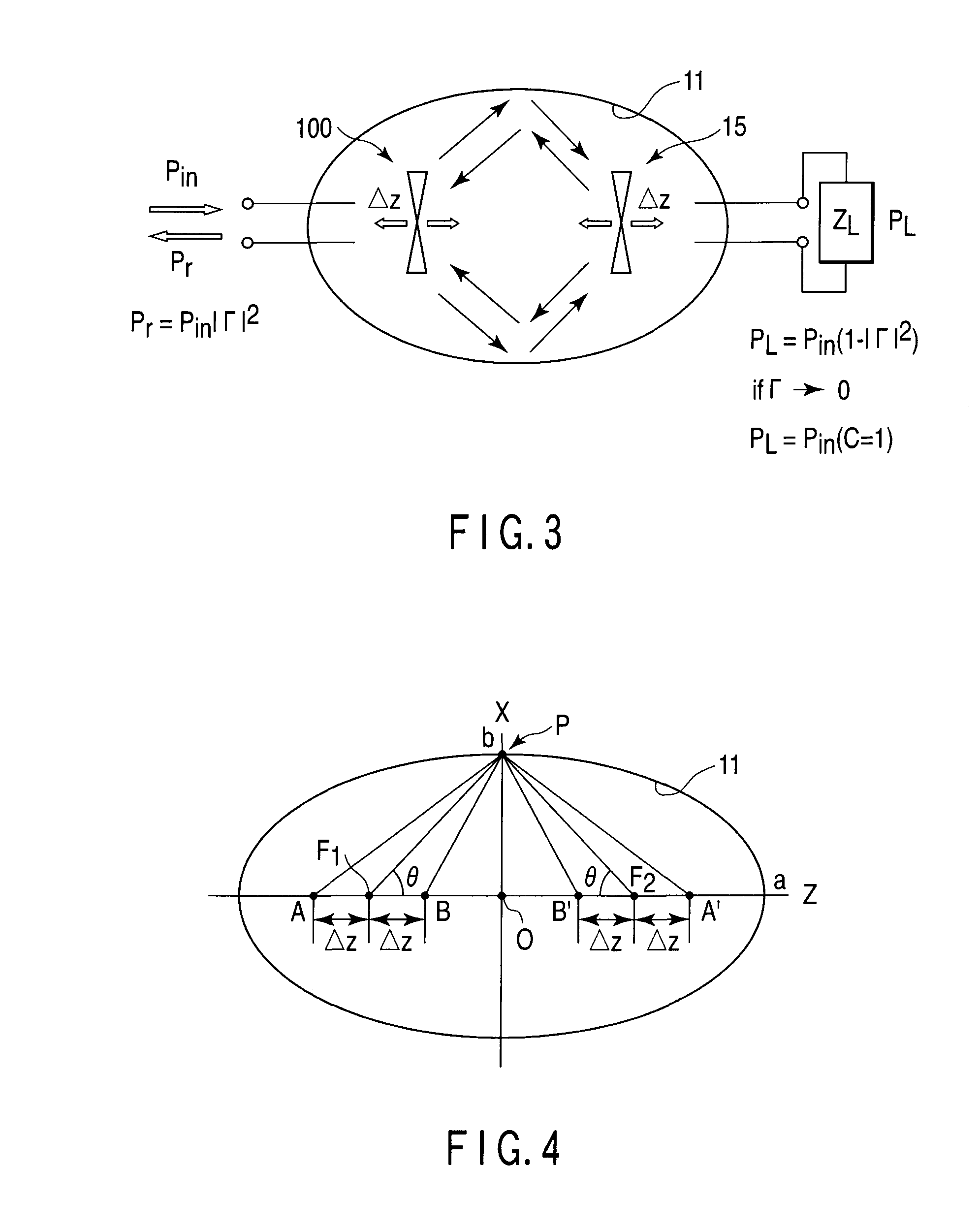
[0195]The radiated power measurement method according to a third embodiment is different from the aforementioned first embodiment in that the process of steps S2 and S3 to start the measurement of the total radiated power at the measurement end of the receiving antenna 15 and complete the measurement is executed not only along the axis (z axis) connecting the first and second focal points F1, F2 but also along other axes (Y and X axes) orthogonal to the Z axis.

[0196]Specifically, in measuring the total radiated power at the measuring end of the receiving antenna 15, the first step is to adjust the position of the DUT 1 along at least selected one of the three-dimensional orthogonal coordinate axes or, for example, a selected axis corresponding to a Y axis orthogonal to the Z axis.

[0197]Next, steps S1 to S4 are executed on the axis along which the position of the DUT 1 is adjusted, and the radiated power is measured and stored in a memory.

[0198]Sim...


PUM


Abstract

In a method of measuring a radiation power generated from a DUT from an output of a measurement antenna, wherein the DUT is arranged in an ellipsoid enclosed space such that a radiation center of the radio wave is substantially coincided with the neighborhood of a first focal point. The radio wave radiated from the DUT and reflected from the wall surface is received by a receiving antenna arranged in the neighborhood a second focal point thereby to measure the total radiated power of the DUT from the output signal of the receiving antenna. One of the DUT and the receiving antenna is moved along the axis passing through the first and second focal points, and based on the measurement value maximizing the output signal power of the receiving antenna, calculating the total radiated power of the DUT.

Description

CROSS REFERENCE TO RELATED APPLICATIONS[0001]This is a Continuation Application of PCT Application No. PCT / JP2009 / 058699, filed May 8, 2009, which was published under PCT Article 21(2) in Japanese.[0002]This application is based upon and claims the benefit of priority from prior Japanese Patent Application No. 2008-123670, filed May 9, 2008, the entire contents of which are incorporated herein by reference.BACKGROUND OF THE INVENTION[0003]1. Field of the Invention[0004]The present invention relates to a method capable of measuring the radiated power with a simple configuration and a small radio terminal in a short time with a high sensitivity, a coupler configured to measure the radiated power and an apparatus configured to measure the radiated power.[0005]2. Description of the Related Art[0006]With the arrival of the ubiquitous society, an explosive extension of ownership of and an increased demand for an ultra small radio terminal such as radio communication devices in terms of th...

Claims


Application Information

Patent Timeline
Patent Type & Authority Applications(United States)
IPC IPC(8): G01R29/08
CPCG01R29/0821H04B17/327H04B17/318H04B17/21
Inventor TESHIROGI, TASUKUHINOTANI, AYAKAWAMURA, TAKASHISAKUMA, TORU
Owner ANRITSU CORP
Why Eureka
Try Eureka