Motion detection method, apparatus and system

a motion detection and motion detection technology, applied in the field of video image processing, can solve the problems of only applicable methods, limited sites where such a system can be used, and inability to make accurate statistics on the passenger flow, so as to reduce the computational complexity of motion detection and high precision

Active Publication Date: 2011-02-24
HISENSE
View PDF6 Cites 131 Cited by
  • Summary
  • Abstract
  • Description
  • Claims
  • Application Information

AI Technical Summary

Benefits of technology

[0012]To solve the problems of the prior art, a motion detection method, apparatus and system are provided in embodiments of the present inve

Problems solved by technology

However, this method cannot make statistics on the passenger flow in an accurate and timely way, especially in rush hours when there is a very large passenger flow; moreover, sites where such a system can be used are limited.
However, such methods are only applicable to situations where the background is relatively simple and fail to make a correct recognition if there are side-by-side objects or objects are crowded in succession.
However, there are still some problems with the prior arts.
The depth information can only assist in removing the false round objects but cannot result in complete removal of the false round objects, so this method suffers from poor detection accuracy, leading to an inaccurate statistical result of the pas

Method used


Image

  • Motion detection method, apparatus and system
  • Motion detection method, apparatus and system
  • Motion detection method, apparatus and system

Examples


first embodiment

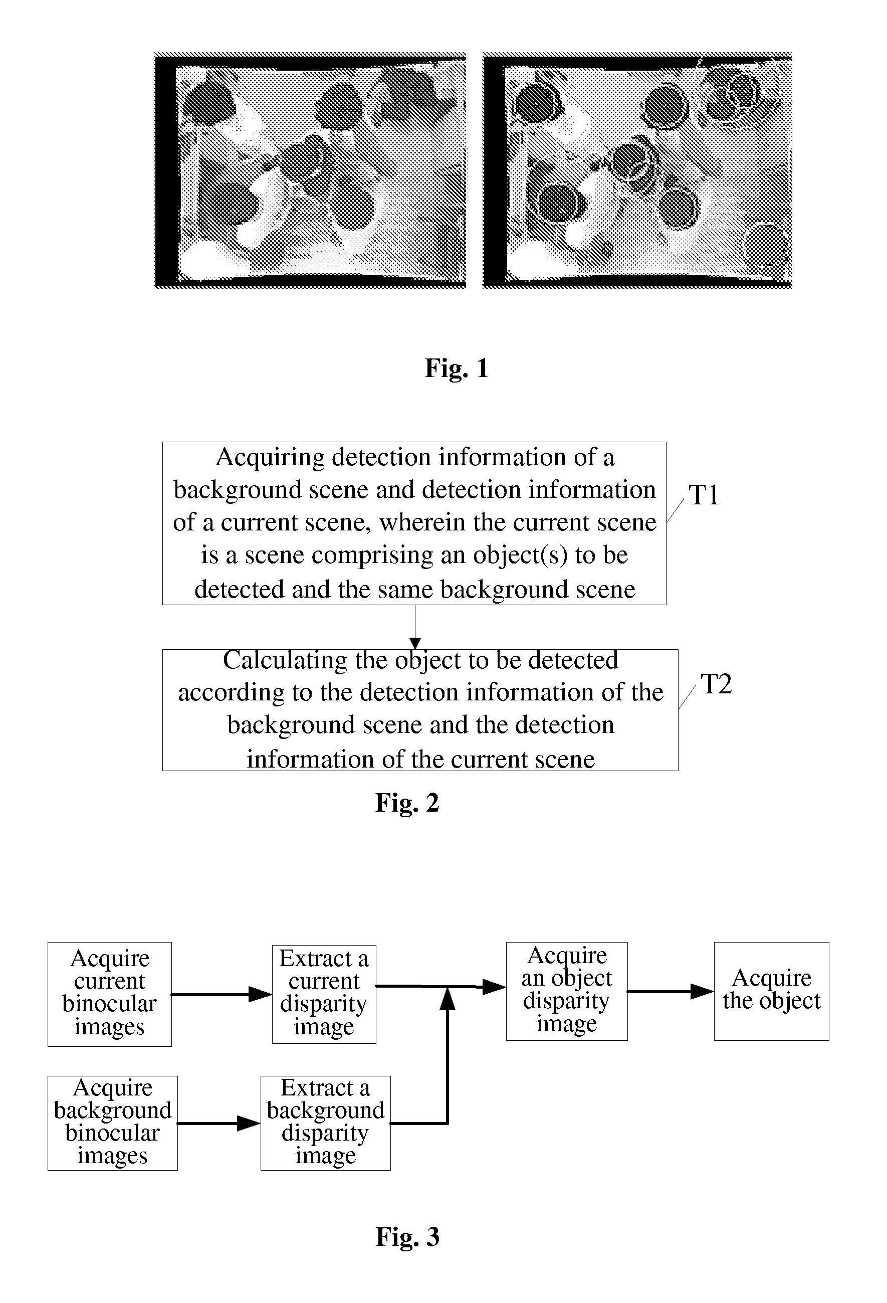
[0085]the present invention provides a motion detection method. As shown in FIG. 2, the method comprises:

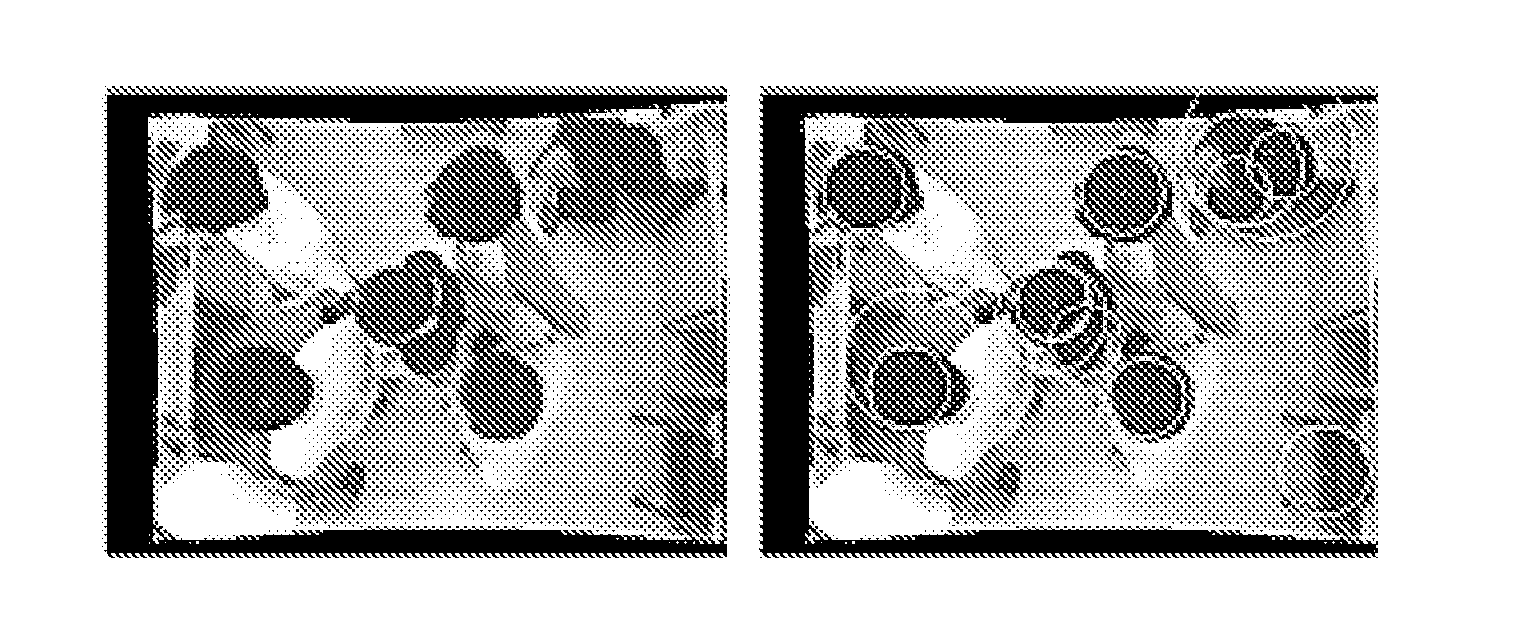
[0086]Step T1: acquiring detection information of a background scene and detection information of a current scene. The current scene is a scene comprising an object(s) to be detected and the same background scene. For example, in an automatic passenger flow statistical system, the background scene is a scene without containing any passengers, while the current scene is a scene containing a passenger flow.

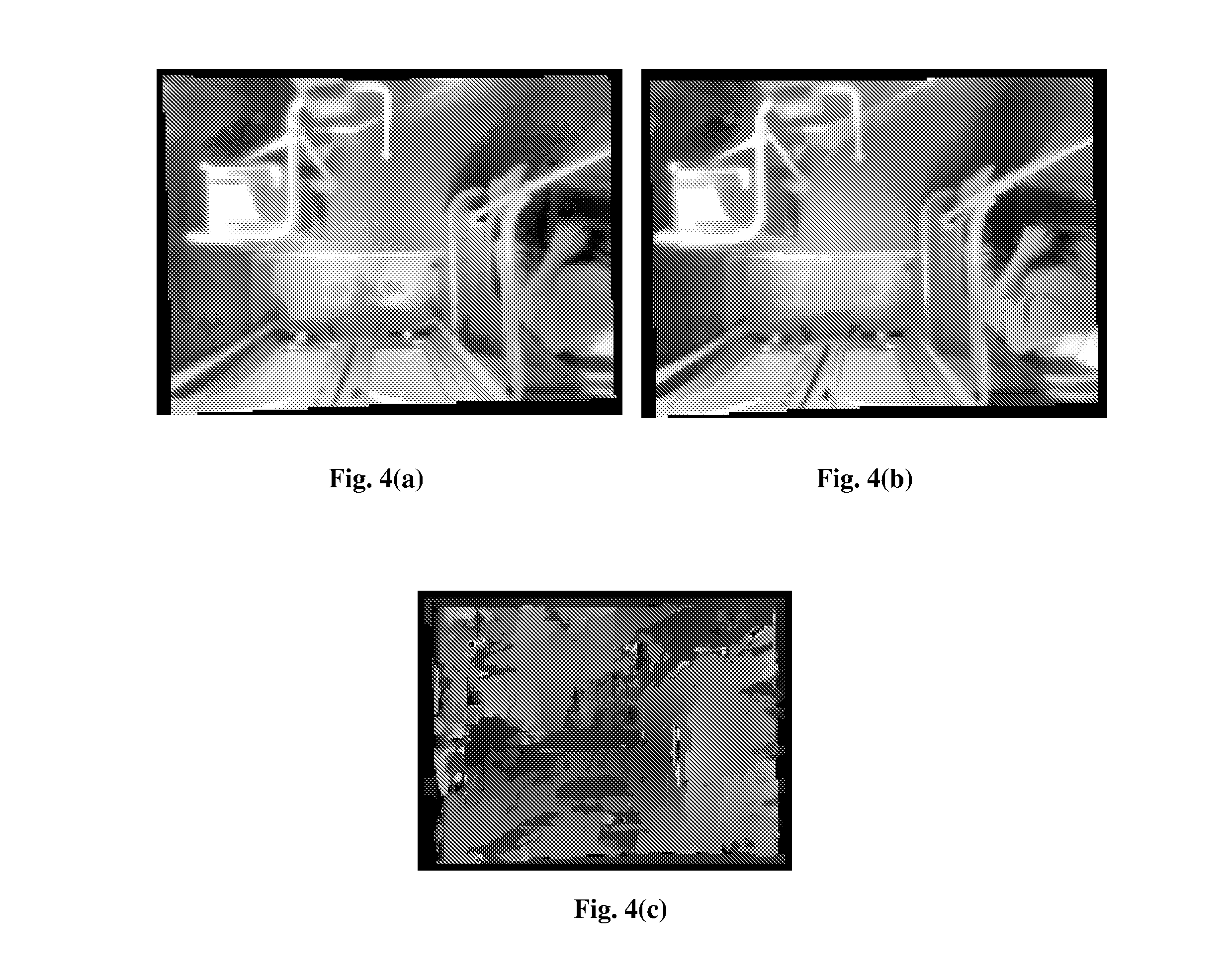
[0087]The detection information described above may be a disparity image or a depth image. In the first embodiment of the present invention, images at different view points may be used to calculate a disparity image. Referring to FIG. 3, firstly, a first image and a second image are acquired from the scene, one of which is a matching image and the other is a matched image. Then, a disparity image of the scene is acquired from the first image and the second image. There is no limi...

second embodiment

[0105]Now, the stereo matching approach provided in the present will be described. Specifically, this approach comprises the following steps:

[0106]Step S11: Selection of key points

[0107]Initially, key points are selected in the left image and the right image. A key point shall be a pixel point that has an obvious feature in the left image and the right image and can be correctly recognized and extracted in an easy way. The key points have an influence on subsequent stereo matching of other points in the images, so they must be selected properly. Considering that points having obvious features in an image are generally located at edges of an object(s), image edge points are preferably selected as key points in this embodiment of the present invention. Edges of the left image and the right image are extracted respectively, and extracted edge points are used as the key points. However, the present invention is not merely limited thereto, and other points having obvious features may als...

fourth embodiment

[0208]As shown in FIG. 9, the present invention provides a motion detection apparatus, which comprises:

[0209]a detection information acquisition unit 91, configured to acquire detection information of a background scene and detection information of a current scene, wherein the current scene is a scene comprising an object(s) to be detected and the same background scene;

[0210]an object detection unit 92, configured to calculate the object(s) to be detected according to the detection information of the background scene and the detection information of the current scene.

[0211]The object detection unit 92 is further configured to calculate the object to be detected by subtracting the detection information of the background scene from the detection information of the current scene; or

[0212]the object detection unit 92 is further configured to set a first weight value, a second weight value and a compensation factor, subtract a product of the detection information of the background scene ...


PUM


Abstract

A motion detection method, apparatus and system are disclosed in the present invention, which relates to the video image processing field. The present invention can effectively overcome the influence of the background on motion detection and the problem of object “conglutination” to avoid false detection, thereby accomplishing object detection in complex scenes with a high precision. The motion detection method disclosed in embodiments of the present invention comprises: acquiring detection information of the background scene and detection information of the current scene, wherein the current scene is a scene comprising an object(s) to be detected and the same background scene; and calculating the object(s) to be detected according to the detection information of the background scene and the detection information of the current scene. The present invention is applicable to any scenes where moving objects need to be detected, e.g., automatic passenger flow statistical systems in railway, metro and bus sectors, and is particularly applicable to detection and calibration of objects in places where brightness varies greatly.

Description

[0001]This application claims priority of China Patent Application No. 200910135766.X filed in China Intellectual Property Office on Apr. 28, 2009 and entitled “Motion Detection Method, Apparatus and System”, which is incorporated herein by reference in its entirety.BACKGROUND OF THE INVENTION[0002]1. Technical Field[0003]The present invention relates to the field of video image processing, and more particularly, to a motion detection method, a motion detection apparatus and a passenger flow detection system.[0004]2. Description of Related Art[0005]In public transportation systems such as railway systems, metro systems and bus systems, by using an automatic passenger flow information statistical system to collect details about the direction, time, volume and distribution of passenger flow in individual routes and stations, it will be made easier for operators to make adjustment on the routes and arrange vehicle resources reasonably.[0006]A conventional method of automatically making...

Claims


Application Information

Patent Timeline
IPC IPC(8): G06K9/00
CPCG06T7/2053G06T7/2086G06T2207/10021G06T2207/10028G06T7/0097G06T2207/20148G06T2207/30196G06T2207/30232G06T2207/30242G06T2207/20144G06T7/174G06T7/254G06T7/285G06T7/194G06T7/136
Inventor LIU, WEIHU, SHUOLIU, SHAO
Owner HISENSE
Why Eureka
Try Eureka