
Fiber Reinforced Plastic-Structure and a Method to Produce the Fiber Reinforced Plastic-Structure

a fiber reinforced plastic and fiber reinforced technology, applied in the field of fiber reinforced plastic structure and a method to produce fiber reinforced plastic structure, can solve the problems of crack formation, weakening of the resulting structure, and application of glue-paste, and achieve the effect of easy control of the thickness and the quality of the bonding zon

Inactive Publication Date: 2011-02-24
SIEMENS AG
View PDF64 Cites 10 Cited by
  • Summary
  • Abstract
  • Description
  • Claims
  • Application Information

AI Technical Summary

Benefits of technology

"The invention provides an improved fiber reinforced plastic-structure and a method to produce it. The structure is made up of at least two single elements that are connected by an applied glue or resin. A mat made of chopped fibers is used between the elements to prevent cracks from forming and propagating in the connection zone. The use of the mat results in a strong and robust connection between the elements, which is much stronger than previous methods. The fiber reinforced plastic-structure can be used to build wind-turbbine blades, and the glue or resin can be applied using a process called VART. The mat is made of pre-impregnated fibers with a random orientation, which results in a high-quality glue-bond with a high inter laminar shear strength. The thickness and quality of the bond-zone can be controlled easily, and air-bubbles and voids are reduced."

Problems solved by technology

This is weakening the resulting structure.
One disadvantage of this filler-based glue is, that its application is done in the shape of a glue-paste.
This often creates voids and air bubbles along the glue line, leading to a crack formation.
Often a glue-paste will result in a brittle glue-line and in a glue line, which shows cracks.

Method used


Image

  • Fiber Reinforced Plastic-Structure and a Method to Produce the Fiber Reinforced Plastic-Structure
  • Fiber Reinforced Plastic-Structure and a Method to Produce the Fiber Reinforced Plastic-Structure
  • Fiber Reinforced Plastic-Structure and a Method to Produce the Fiber Reinforced Plastic-Structure

Examples


Embodiment Construction

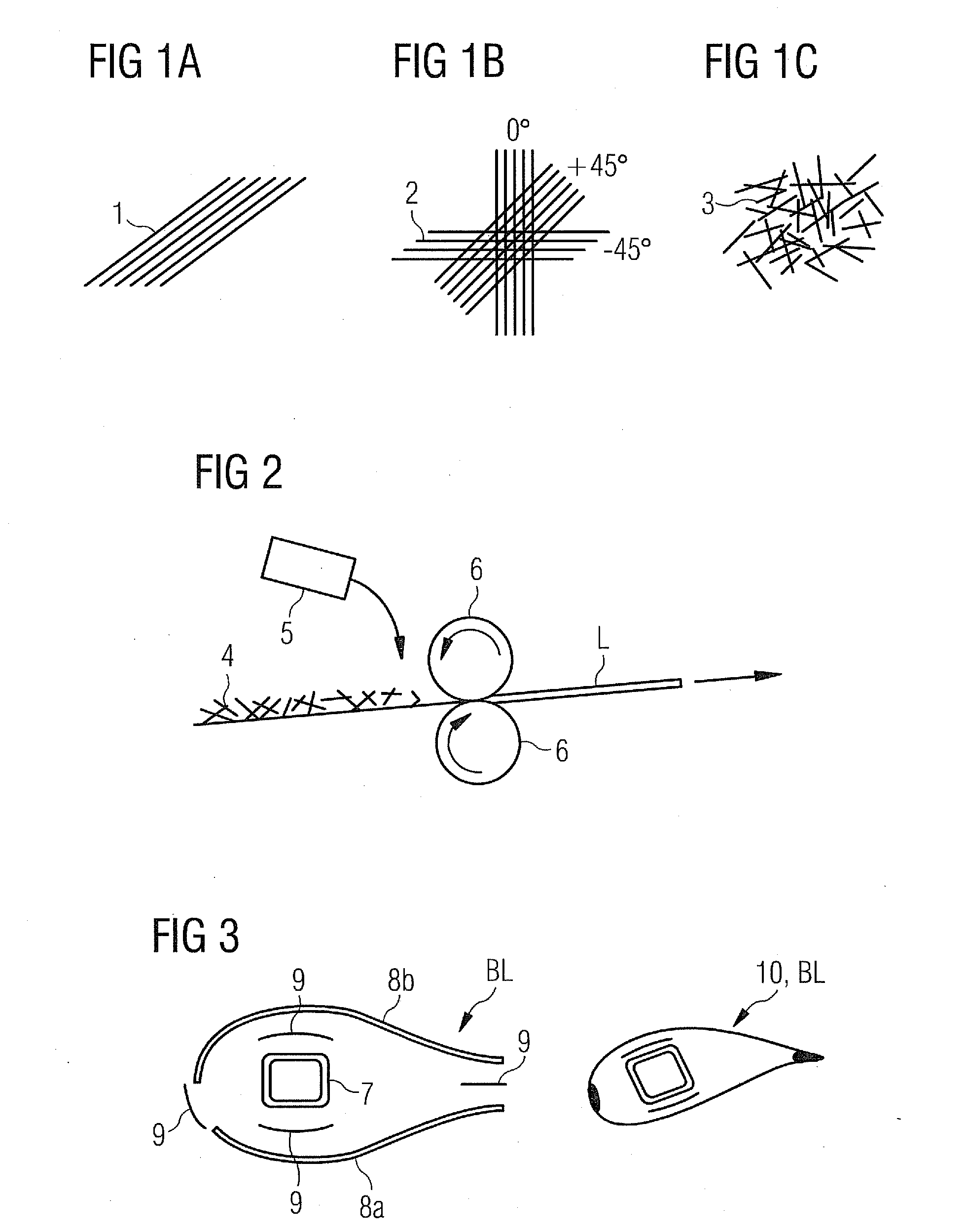
[0040]FIG. 1A shows a unidirectional laminate 1, comprising a number of fibers, which are aligned in a parallel direction. The laminate shows therefore a high specific stiffness along its length.

[0041]The laminate 1 shows a very smooth surface, which might lead to an impaired inter laminar shear strength value for a glue connection to the final laminate 1.

[0042]FIG. 1B shows a multidirectional laminate 2, comprising a first number of fibers, which are aligned in a 0° direction. A second number of fibers are controlled aligned in a +45° direction while a third number of fibers are controlled aligned in a −45° direction.

[0043]The resulting laminate 2 shows an improved specific stiffness in the relevant directions 0°, +45° and −45°.

[0044]The laminate 2 shows a very smooth surface, which might lead to an impaired inter laminar shear strength value for a glue connection to the final laminate 2.

[0045]FIG. 1C shows a laminate 3, comprising random-oriented, cut fibers. These fibers are form...


PUM

PropertyMeasurementUnit
lengthaaaaaaaaaa
lengthaaaaaaaaaa
plasticaaaaaaaaaa

Abstract

A fiber reinforced plastic-structure and to a method to produce the fiber reinforced plastic-structure are disclosed. At least two elements are used to build up the shape of the fiber reinforced plastic-structure. Two adjacent elements are connected via its contact-surfaces by an applied glue or resin. A mat is located between the contact-surfaces before the glue or resin is used to connect the elements. The mat comprises chopped fibers, which are oriented in a random manner.

Description

CROSS REFERENCE TO RELATED APPLICATIONS[0001]This application claims priority of European Patent Office application No. 09010467.0 EP filed Aug. 20, 2009, which is incorporated by reference herein in its entirety.FIELD OF INVENTION[0002]The invention relates to a fiber reinforced plastic-structure and to a method to produce the fiber reinforced plastic-structure, while at least two elements are used to build up the shape of the fiber reinforced plastic-structure.BACKGROUND OF INVENTION[0003]It is known to build up a wind-turbine-blade for example by the use of fiber-reinforced laminates. The fiber-reinforced laminates may consist of chopped strand mats (CSM) or of woven fabric mats (like multi-axis interlaid scrims), of warp-thread reinforced unidirectional performs, of single or joined roving bundles and of any known fiber-material like glass, Kevlar, carbon or hemp.[0004]The fiber-reinforcement may be supplemented with pre-fabri-cated components. For example fiberglass inserts, pu...

Claims


Application Information

Patent Timeline
Patent Type & Authority Applications(United States)
IPC IPC(8): B32B5/26B29C45/14B32B5/16B32B27/38B32B27/04B29C70/36
CPCB29L2031/085Y02E10/721B32B2603/00B32B17/04Y02E10/72Y10T428/24995Y10T428/31504Y10T428/31515Y02P70/50
Inventor GROVE-NIELSEN, ERIK
Owner SIEMENS AG
Learn More