
Coordinated action robotic system and related methods

a robotic system and robotic system technology, applied in the field of robotic vehicles, can solve the problems of limited control of robots, limited dexterity and movement of robots, and difficulty for operators to control each robot, and achieve the effect of increasing dexterity

Active Publication Date: 2011-02-24
HARRIS CORP
View PDF31 Cites 73 Cited by
  • Summary
  • Abstract
  • Description
  • Claims
  • Application Information

AI Technical Summary

Benefits of technology

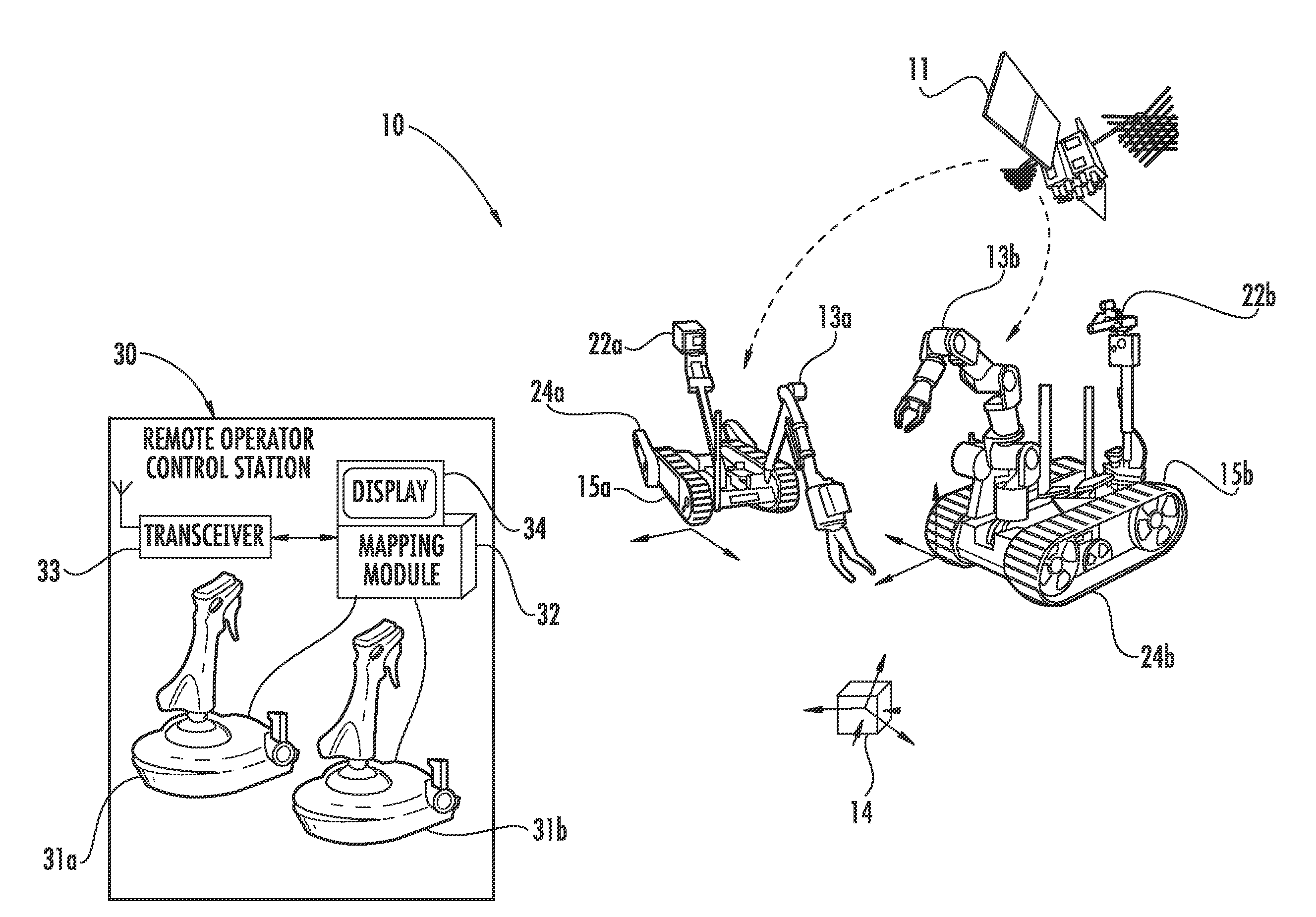
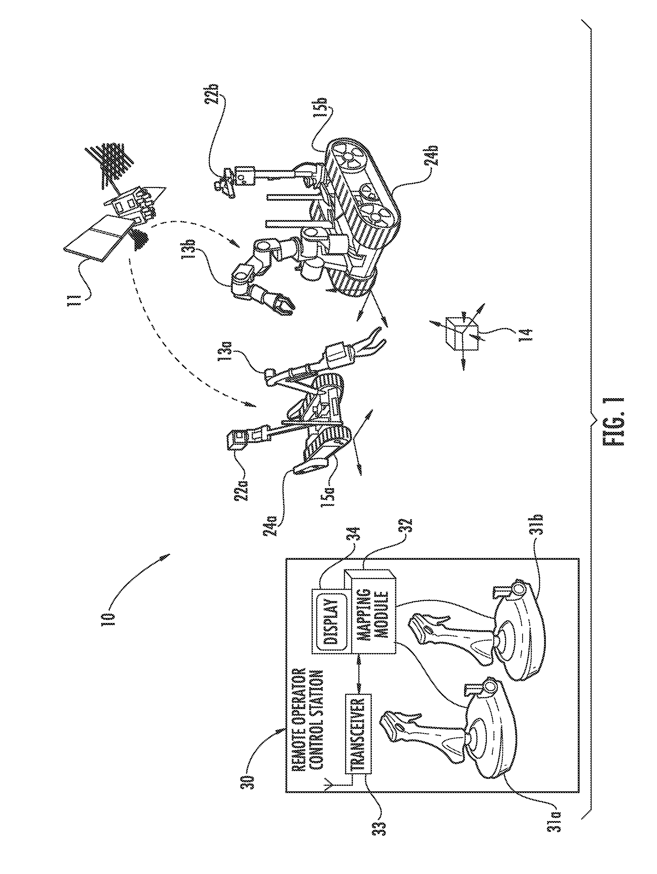
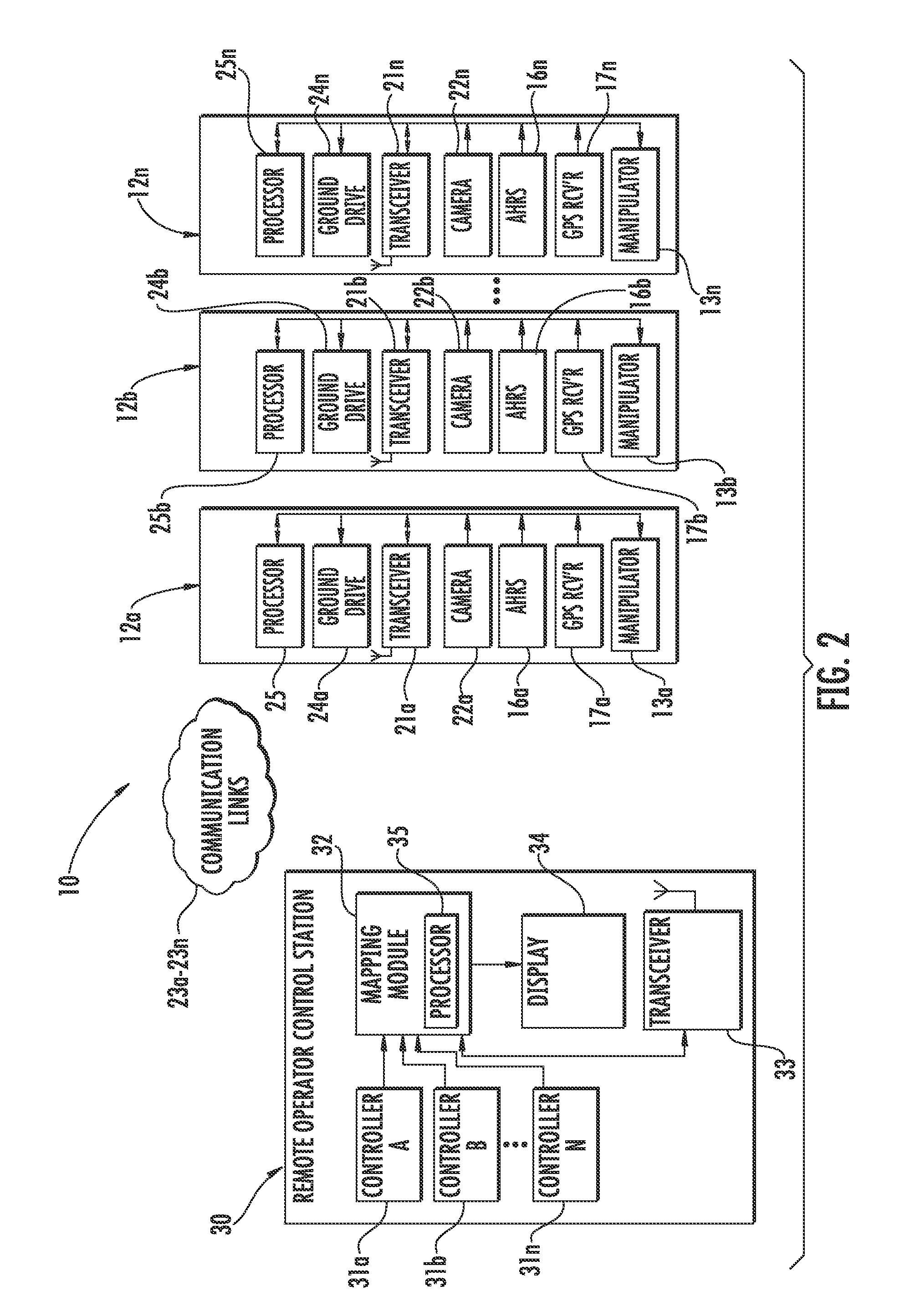
[0008]This and other objects, features, and advantages in accordance with the present invention are provided by a coordinated action robotic system that includes a plurality of robotic vehicles. Each of the plurality of robotic vehicles may include a platform and at least one manipulator movable relative thereto. The robotic system may also include a remote operator control station that may include a respective controller for each manipulator, for example. The remote operator control station may further include a mapping module to map movement of each manipulator relative to its platform so that operation of the controllers for manipulator movement in a given direction produces corresponding movement of the respective manipulators in the given direction. Accordingly, the coordinated action robotic system provides coordinated robotic vehicle manipulator movements, and thus increased dexterity thereof.

Problems solved by technology

Reduced cost and reduced weight may correspond to limited robot functions.
Control of a robot may be limited by a number of ways the robot may be manipulated.
More particularly, for example, a robot may have limited dexterity and limited movement in a finite number of directions as a result.
Moreover, when more than one robot having limited dexterity and limited movement is used, it may be difficult for an operator to control each robot.
More particularly, when each robot's platform is positioned in a different direction, an operator may find it increasingly difficult to control respective manipulators in a common direction or have coordinated movements from a controller correspond to coordinate movements of the respective manipulators.

Method used


Image

  • Coordinated action robotic system and related methods
  • Coordinated action robotic system and related methods
  • Coordinated action robotic system and related methods

Examples


Embodiment Construction

[0020]The present invention will now be described more fully hereinafter with reference to the accompanying drawings, in which preferred embodiments of the invention are shown. This invention may, however, be embodied in many different forms and should not be construed as limited to the embodiments set forth herein. Rather, these embodiments are provided so that this disclosure will be thorough and complete, and will fully convey the scope of the invention to those skilled in the art. Like numbers refer to like elements throughout, and prime notation is used to indicate similar elements in alternative embodiments.

[0021]Referring initially to FIGS. 1 and 2, a coordinated action robotic system 10 illustratively includes a plurality of robotic vehicles 12a-12n. Each of the plurality of robotic vehicles 12a-12n includes a platform 15a-15n and a manipulator 13a-13n movable relative thereto. As will be appreciated by those skilled in the art, each robotic vehicle 12a-12n may include more ...


PUM


Abstract

A coordinated action robotic system may include a plurality of robotic vehicles, each including a platform and at least one manipulator movable relative thereto. The robotic system may also include a remote operator control station that may include a respective controller for each manipulator. The remote operator control station may also include a mapping module to map movement of each manipulator relative to its platform. Operation of the controllers for manipulator movement in a given direction produces corresponding movement of the respective manipulators in the given direction such that the robotic vehicles may be controlled as if they were one robotic vehicle. The coordinated movement may result in increased operational efficiency, increased operational dexterity, and increased ease of controlling the robotic vehicles.

Description

FIELD OF THE INVENTION[0001]The present invention relates to the field of robotic vehicles, and more particularly, coordinated control of robotic vehicles and related methods.BACKGROUND OF THE INVENTION[0002]A robot may be used for a variety of unmanned operations. One example of an unmanned robot is an unmanned ground vehicle (UGV), for example, the iRobot Packbot, available from iRobot of Bedford, Mass. A UGV may typically include a platform, and a manipulator carried by the platform that is often primitive and includes joint level control. The single manipulator often performs all of the operations.[0003]A commercial-off-the-shelf robot may have increased flexibility and may include dual arm, dexterous manipulators. One particular example is the MotoMan DIA 10, available from Motoman, Inc. of West Carrollton, Ohio. Academia and research groups may also provide robots with increased functionality, for example, the NASA Robonaut.[0004]U.S. Pat. No. 6,898,484 to Lemelson et al. disc...

Claims


Application Information

Patent Timeline
Patent Type & Authority Applications(United States)
IPC IPC(8): G05B19/418
CPCB25J9/162B25J9/1682B25J9/1689G05B2219/39146G05B2219/40171G05B2219/39259G05B2219/39439G05B2219/40161G05B2219/39172
Inventor SUMMER, MATTHEW D.
Owner HARRIS CORP
Learn More