Check patentability & draft patents in minutes with Patsnap Eureka AI!

Structure of a magnetic-field gradient sensor and process for fabricating it in integrated technology

Inactive Publication Date: 2011-02-24
COMMISSARIAT A LENERGIE ATOMIQUE ET AUX ENERGIES ALTERNATIVES
View PDF7 Cites 16 Cited by
  • Summary
  • Abstract
  • Description
  • Claims
  • Application Information

AI Technical Summary

Benefits of technology

[0023]The invention makes it possible, through the presence or adjustment of the distance (offset) Ty of one elementary sensor in relation to the adjacent elementary sensors (preceding and / or following), to reduce the disruptions caused by the proximity of the magnetic portions of the adjacent elementary sensors.
[0024]Preferably, the distance Ty is such that the mutual disruption of the adjacent elementary sensors is low.
[0025]The invention makes it possible to perform a measurement in the case where the component to be measured of the magnetic field is invariant (at least over a short distance) in a direction y perpendicular to the direction z along which one wishes to measure the gradient.
[0026]The invention makes it possible to measure the gradient, or an n-th order derivative less than or equal to N−1, of a component Hx of the field from sensors, in particular when they are very directional, i.e. having strong selectivity of the measurement of a component of the field and also when these field sensors have a magnetic circuit or a flow guide, such as for example micro-fluxgate, magneto-resistance or magneto-impedance sensors.
[0036]Preferably the distance Ty is such that the mutual disruption of the adjacent sensors is low.

Problems solved by technology

The implementation of this technique poses several problems.
The problem then arises of reducing the distances separating these sensors from the conductor 1, as well as the distances separating the sensors from each other, as much as possible.
But if the sensors are miniaturized, their environment (and in particular their packaging) could impose minimal dimensional constraints, which can sometimes be bothersome, as in the configuration of FIG. 5 described in document U.S. Pat. No. 6,154,023.
It is therefore difficult, in certain cases, to reduce the distance d between the different sensors.
Yet the magnetic circuits of these sensors disrupt each other when the sensors are brought too close, resulting in a less precise measurement.
Moreover, if they are very directional (which is advantageous to perform a non-noisy measurement), they must be parallel to each other, which is very delicate to achieve with discrete sensors, in particular when they are miniaturized.
Another problem arises during use of a gradient sensor in an industrial environment.
In this context it may sometimes be necessary to use the sensor inside a magnetic shielding, which, although it has the advantage of reducing disrupting fields, also has the drawback of creating a relatively significant field gradient in its immediate vicinity.
The problem then arises of having a gradient sensor small enough to avoid one of the elementary sensors making it up being too close to the shielding, which could disrupt the measurement.
The problem also arises of being able to have a sensor structure that can be made in collective technology, for example with machines of the types used in microelectronics or micro- or nano-technologies.

Method used


Image

  • Structure of a magnetic-field gradient sensor and process for fabricating it in integrated technology
  • Structure of a magnetic-field gradient sensor and process for fabricating it in integrated technology
  • Structure of a magnetic-field gradient sensor and process for fabricating it in integrated technology

Examples


Embodiment Construction

[0060]The invention can be used for macroscopic sensors as well as miniaturized / integrated sensors. But it is particularly well adapted to an implementation of sensors of the type developed in microtechnology.

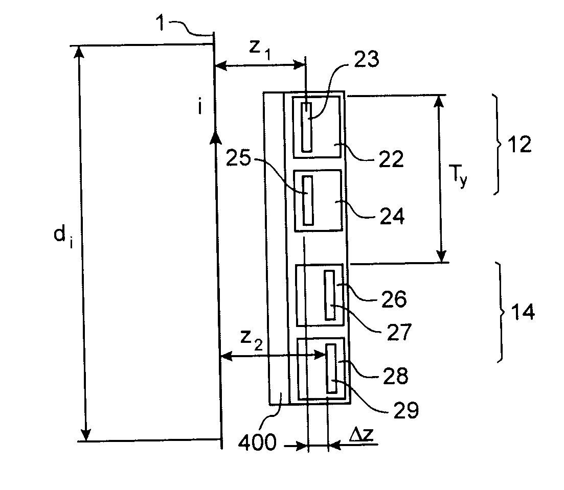
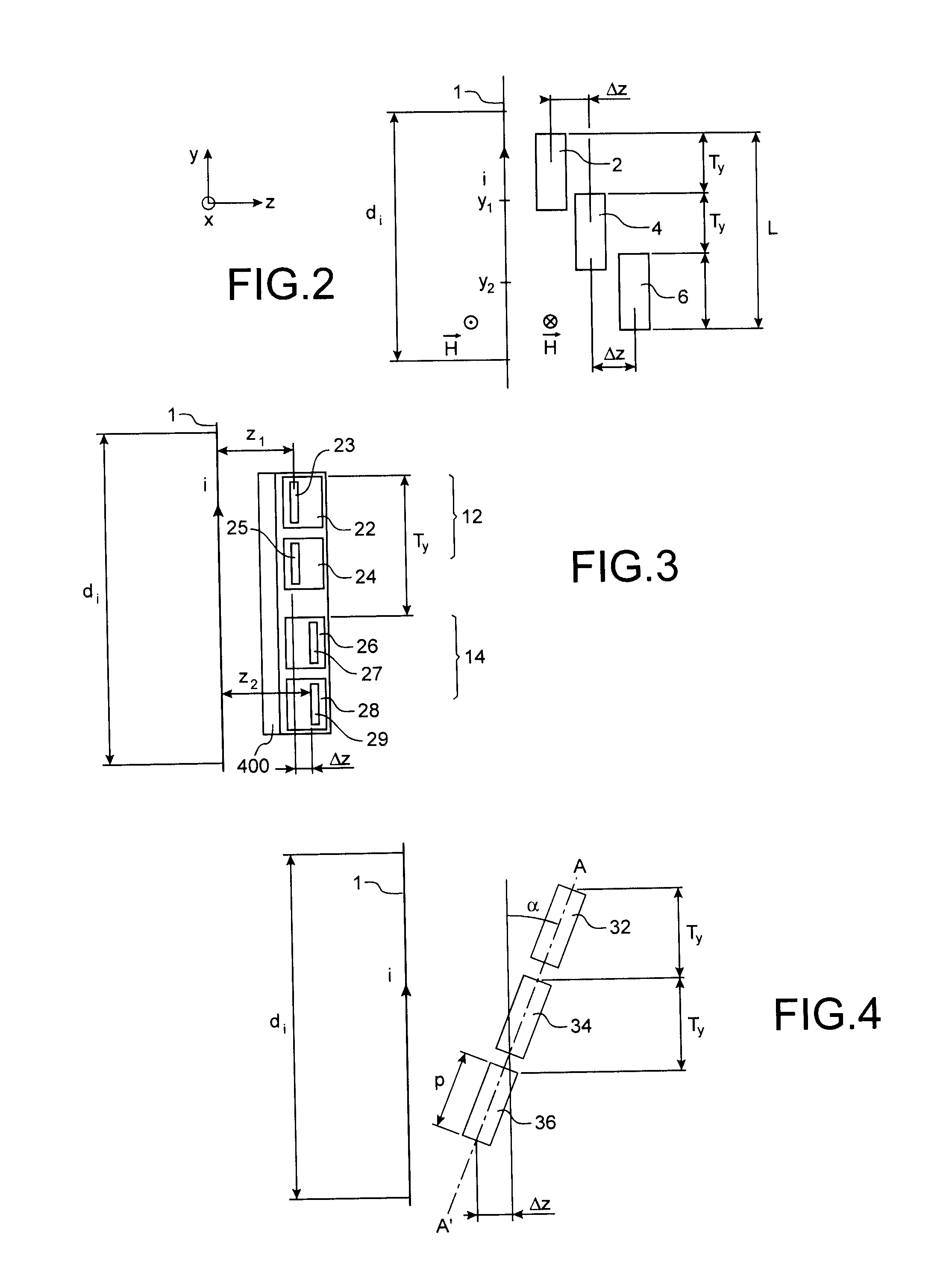
[0061]A first embodiment of the invention is shown in FIG. 2.

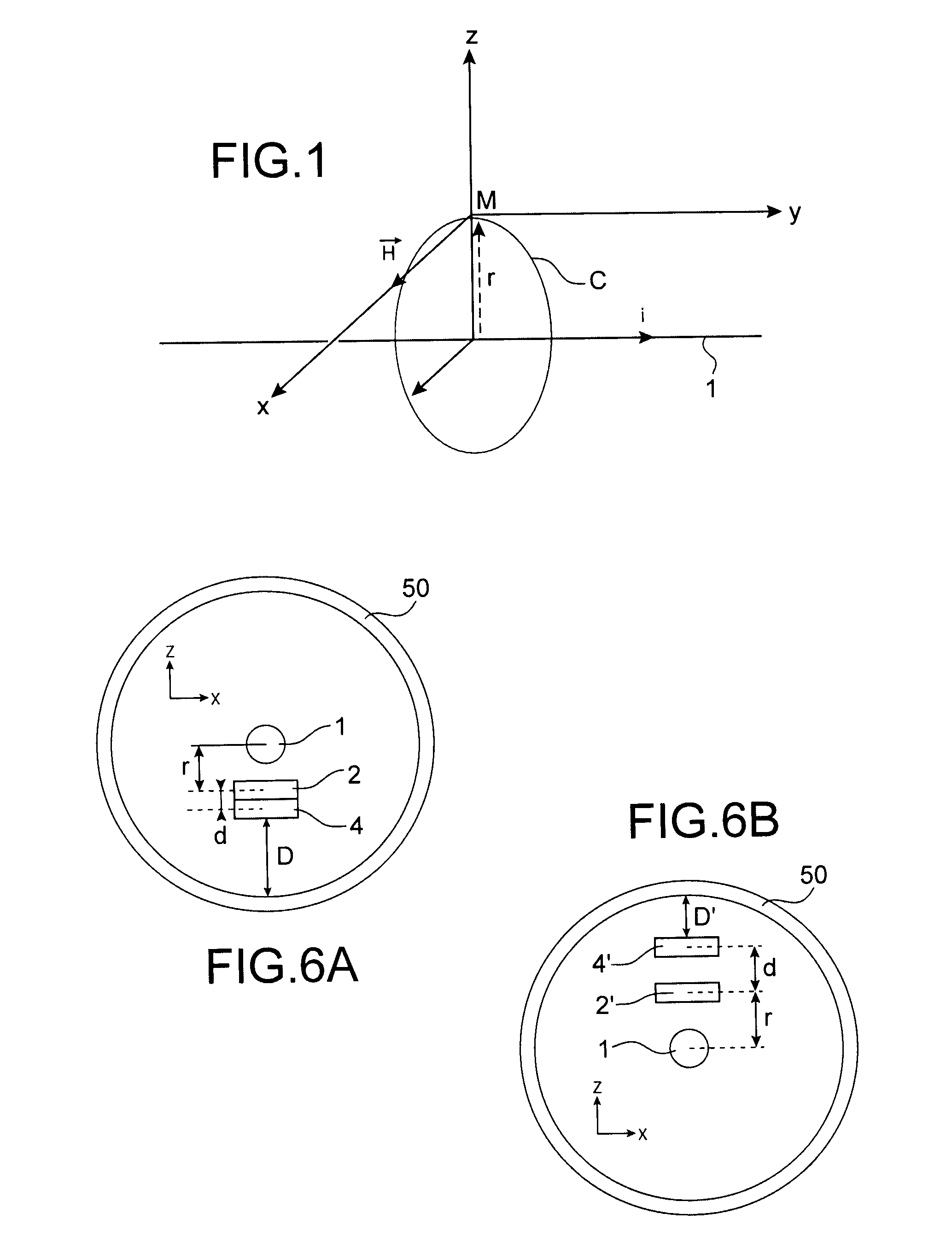
[0062]In that figure, a conductor 1 is aligned in a direction Oy in a reference Oxyz. The current i circulating there creates a magnetic field H in the surrounding space, this field having components Hx, Hy, Hz in the chosen reference.

[0063]The elementary sensors 2, 4, 6 of this figure illustrate the case where N=3 sensors, making it possible to measure derivatives up to the n=N−1=2 order. Each elementary sensor can for example advantageously be chosen as a micro-fluxgate magnetometer, with 1 or 2 cores, oriented along the x axis and the thickness of which goes along the z axis.

[0064]This structure according to the invention makes it possible to measure the gradient of a component of the field H, here Hx, along direct...


PUM


Abstract

A process for measuring the gradient or an n-th order derivative, in which n is greater than 1, in a direction z, of a component Hx of a magnetic field, the component being invariant, at least locally, in a direction y. The method includes: a) positioning of N (N>n+1) elementary field sensors, each sensor being offset, relative to the neighboring sensors, along y by a distance Ty and along the z axis by a distance Δz, b) measurement of the field by each of the N sensors, and c) calculation of the desired gradient, or the desired nth-order derivative, as a function of the measurements of the field obtained during b).

Description

TECHNICAL FIELD AND BACKGROUND OF THE INVENTION[0001]The invention concerns a device for measuring the gradient of a component of a magnetic field (excitation H or induction B), a process for measuring said gradient, and a process for producing said device. Such a device can be produced in integrated form.[0002]This invention applies in particular to measuring electrical current in filiform conductors.[0003]Known from document WO 03044541 is a method for measuring a current in a conductor, implementing the measurement of n-th order derivatives of the magnetic field. This method makes it possible in particular to reduce the disruptions caused by parasitic conductors.[0004]Let xyz be an orthonormal reference, shown in FIG. 1, centered at the point M where one wishes to conduct the measurement, and where y is parallel to the axis of the conductor 1 (and situated in plane yMz). The z axis is colinear to the radius perpendicular to the conductor passing through M and x is tangent to the ...

Claims


Application Information

Patent Timeline
IPC IPC(8): G06F19/00G01R19/00
CPCG01R15/205G01R33/022
Inventor ALBERTINI, JEAN-BAPTISTE
Owner COMMISSARIAT A LENERGIE ATOMIQUE ET AUX ENERGIES ALTERNATIVES
Features
  • R&D
  • Intellectual Property
  • Life Sciences
  • Materials
  • Tech Scout
  • Unparalleled Data Quality
  • Higher Quality Content
  • 60% Fewer Hallucinations
Learn More