
Aircraft stabilizer actuator

Active Publication Date: 2011-03-03
PARKER INTANGIBLES LLC
View PDF27 Cites 46 Cited by
  • Summary
  • Abstract
  • Description
  • Claims
  • Application Information

AI Technical Summary

Benefits of technology

The present invention provides an actuator that can eliminate a potential single failure mechanism of the ball screw thread found in certain previous designs. The actuator has an architecture that can improve the reliability of the system by reducing the latencies of a structural failure and / or the need for manual periodic inspections of the load transfer assemblies between the airframe and the control surface.
Under normal operating conditions, the coupler engages the drive mechanism to the primary load transfer assembly and the secondary load transfer assembly. The primary load transfer assembly carries the load from the motor to the control surface with the secondary load transfer assembly being generally unloaded. Upon detection of a failure, the coupler can disengage the drive mechanism from the secondary load transfer assembly. The secondary load transfer assembly, which can include a low-efficiency assembly, can therefore be loaded upon failure of the first load transfer assembly. When loaded, the second load transfer assembly, via the low-efficiency assembly, can inhibit movement of the control surface, which may avoid a catastrophic loss of control of the control surface during flight.
Additionally, measurement of the range of movement of the control surface while the coupler is in the open state can provide a measurement of the overall backlash and wear of the actuator, which can be beneficial in the determination of when parts may need to be repaired and / or replaced.

Problems solved by technology

Furthermore, this architecture still has the potential for a single failure mechanism in the complete loss of the ball screw threads, which would result in a loss of control of both nuts and a catastrophic loss of control of the stabilizer.

Method used


Image

  • Aircraft stabilizer actuator
  • Aircraft stabilizer actuator
  • Aircraft stabilizer actuator

Examples


Embodiment Construction

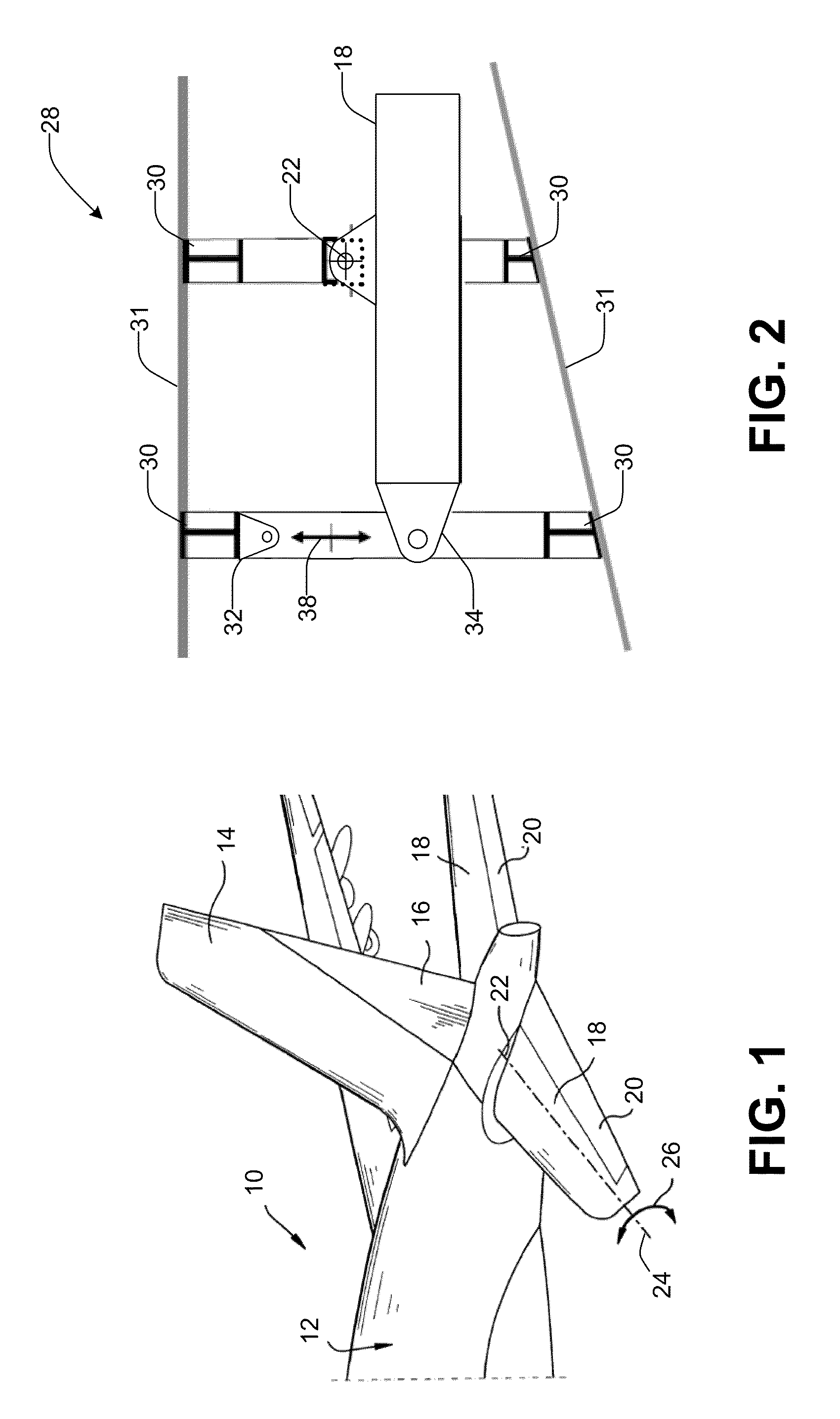
Referring initially to FIG. 1, an aircraft 10 can include a tail portion 12 having a tail fin 14 which carries control surfaces, such as a rudder 16. The horizontal stabilizer 18 is movable and carries control surfaces such as elevators 20. The horizontal stabilizer 18 can be pivotally mounted to the fuselage at pivot point 22 whereby it can be pivoted about axis 24 to adjust the longitudinal pitch (i.e., “trim”) of the aircraft 10 as indicated by arrows 26. During flight, the horizontal stabilizer can be adjusted by an actuator which, in the illustrated embodiment, moves the leading edge of the stabilizer upward / downward relative to the axis 24. The stabilizer adjustments may be automatically controlled directly from the aircraft's flight computers and / or may be manually controlled by pilot input.

With additional reference to FIG. 2, a portion of the airframe 28 of the tail portion 12 of the aircraft 10 is shown. The airframe 28 can include a plurality of supporting ribs 30 that sup...


PUM


Abstract

An actuator for actuating movement of a control surface relative to a structure can include a high-efficiency assembly and a low-efficiency assembly. The high-efficiency assembly can be connectable between a control surface and a structure for providing a first load transfer assembly and the assembly can have minimum backlash. The low-efficiency assembly is connectable between the control surface and the structure for providing a second load transfer assembly. The low-efficiency or irreversible assembly can be disposed in parallel relationship to the high-efficiency assembly and can have a higher backlash than the low-efficiency assembly. The low-efficiency assembly can be unloaded in normal operation. The actuator also can include a coupler for that can have a closed state in which both load transfer assemblies are synchronously driven by the drive mechanism, and an open state in which the drive mechanism is decoupled from the low-efficiency assembly and the low-efficiency assembly can inhibit movement of the control surface.

Description

BACKGROUND OF THE INVENTIONIn a large majority of commercial aircrafts, the position of the horizontal stabilizer is controlled by a single ball screw actuator with two load paths for safety, for example, a tie-rod within a ball screw and two nuts on the screw. The screw, tie-rod and both nuts have independent attachments to the stabilizer that provide first and second load paths which preclude a catastrophic loss of holding capability with a single structural failure. This is a key requirement for the FAA certification of any commercial aircraft. The second load path may only be used to control the stabilizer upon a failure of the first load path.This type of architecture requires periodic manual inspection of the second load path to verify its integrity and to identify potential latent failures. Furthermore, this architecture still has the potential for a single failure mechanism in the complete loss of the ball screw threads, which would result in a loss of control of both nuts a...

Claims


Application Information

Patent Timeline
IPC IPC(8): B64C13/34F16H37/00F16H25/20G01D21/00
CPCB64C5/02B64C13/28Y10T74/18568Y10T74/186F16H25/205B64C13/341
Inventor KEECH, NANCY KAYCYROT, LUC P.POLCUCH, ERIC A.
Owner PARKER INTANGIBLES LLC
Learn More