Fluid supply mechanism for rotary tool

a technology of rotary tools and supply mechanisms, which is applied in the direction of metal sawing equipment, metal-working equipment, metal sawing accessories, etc., can solve the problems of large consumption of fluid, abnormal rise of rotary tools, and reduced life, so as to avoid the influence of cost and working environment, reduce the thickness of the teeth of the former, and improve the rigidity around the teeth.

Inactive Publication Date: 2011-03-03
KANEFUSA HAMONO KOUGIYOU KK
View PDF9 Cites 16 Cited by
  • Summary
  • Abstract
  • Description
  • Claims
  • Application Information

AI Technical Summary

Benefits of technology

[0017]Even for a circular saw blade having a thick boss type base, the conventional fluid supply mechanism disclosed in the Literature 1 can be utilized as it is only by replacing the shims of the conventional fluid mechanism with the shims of the present invention. As a result, it is possible to avoid the influences on cost and working environment. Inc...

Problems solved by technology

However, there is the disadvantage that the temperature of the rotary tool rises abnormally due to friction during cutting a work, and a base or teeth thereof are broken or distorted to reduce its life.
When the flui...

Method used


Image

  • Fluid supply mechanism for rotary tool
  • Fluid supply mechanism for rotary tool
  • Fluid supply mechanism for rotary tool

Examples


first embodiment

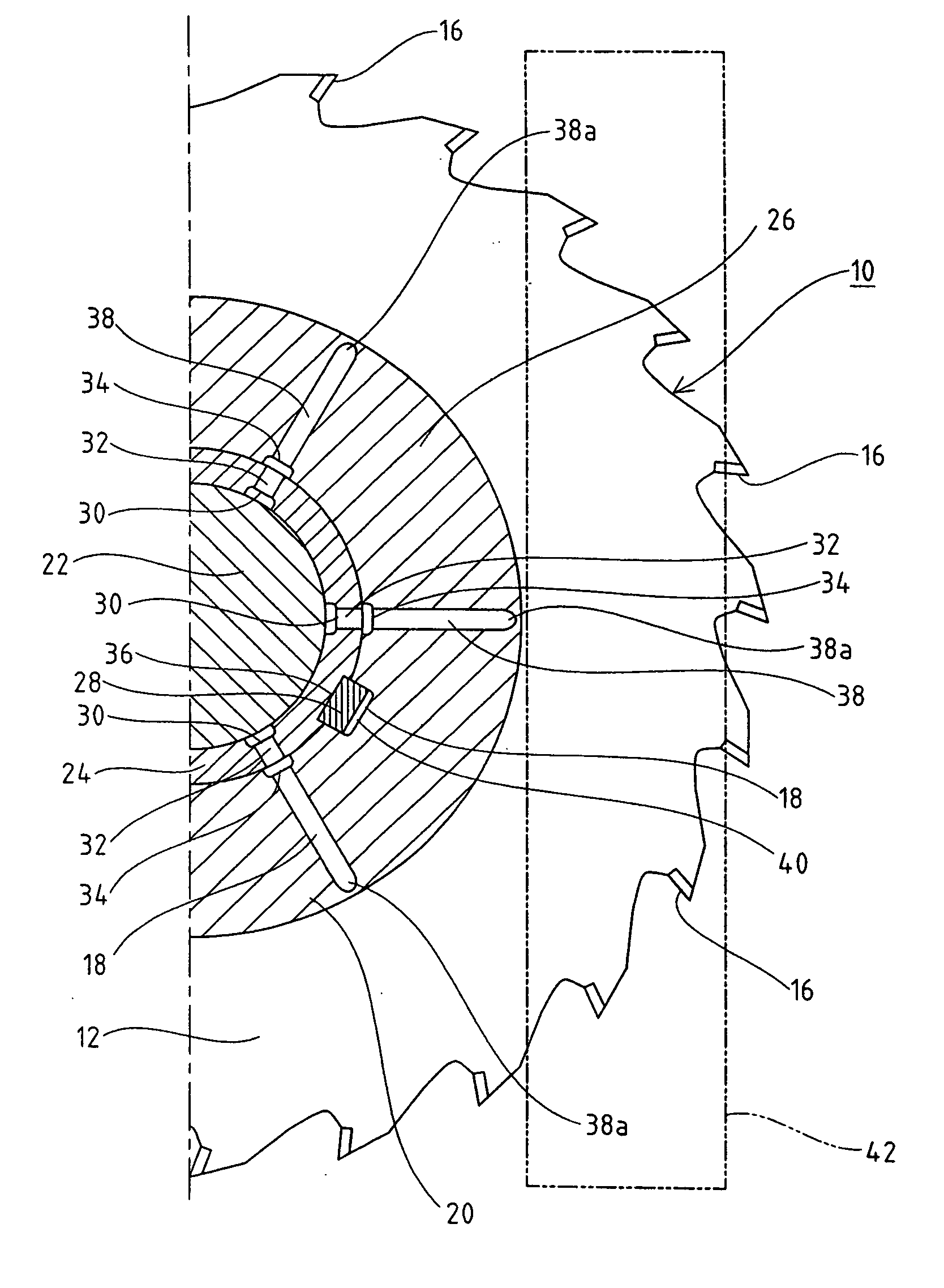
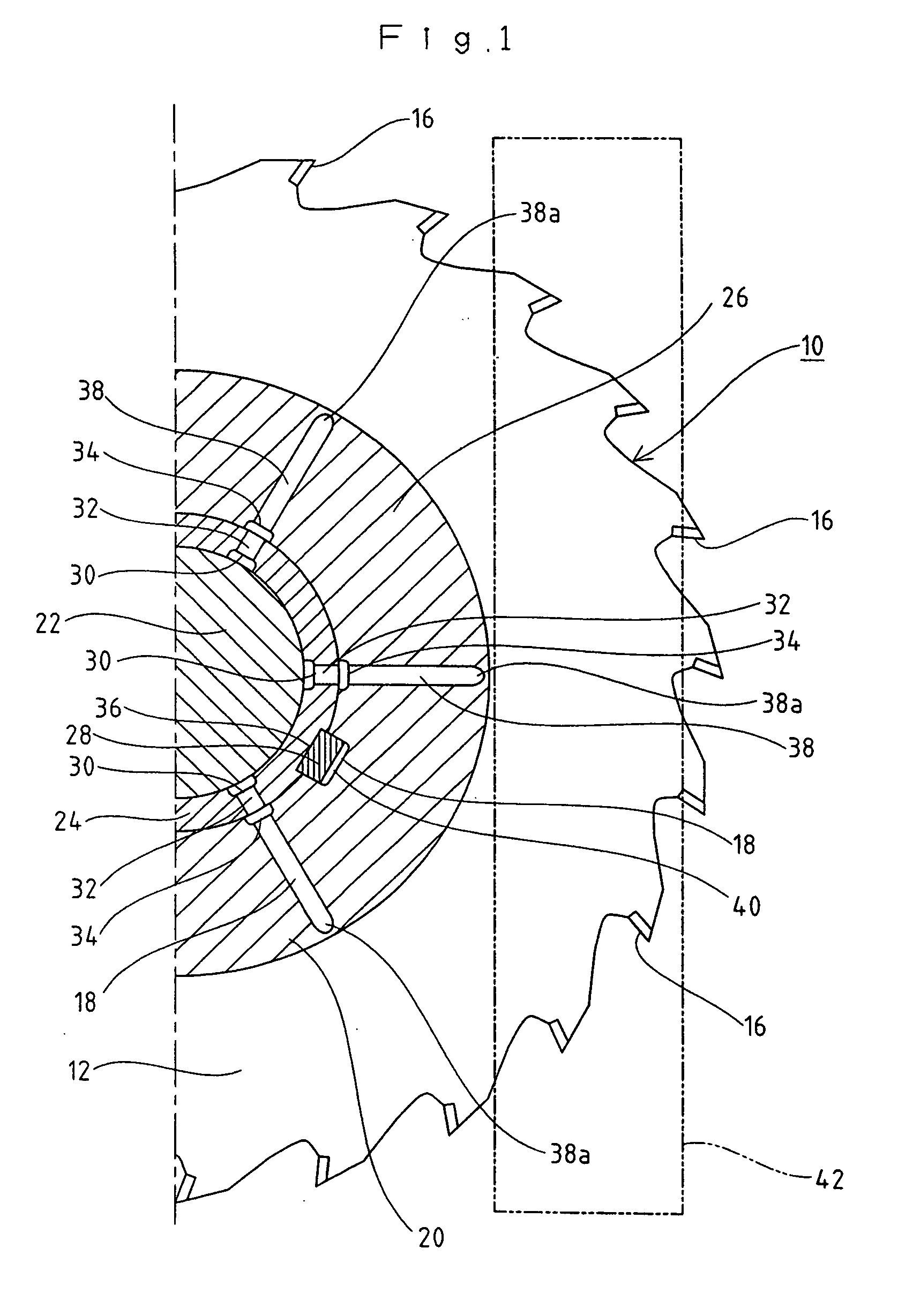
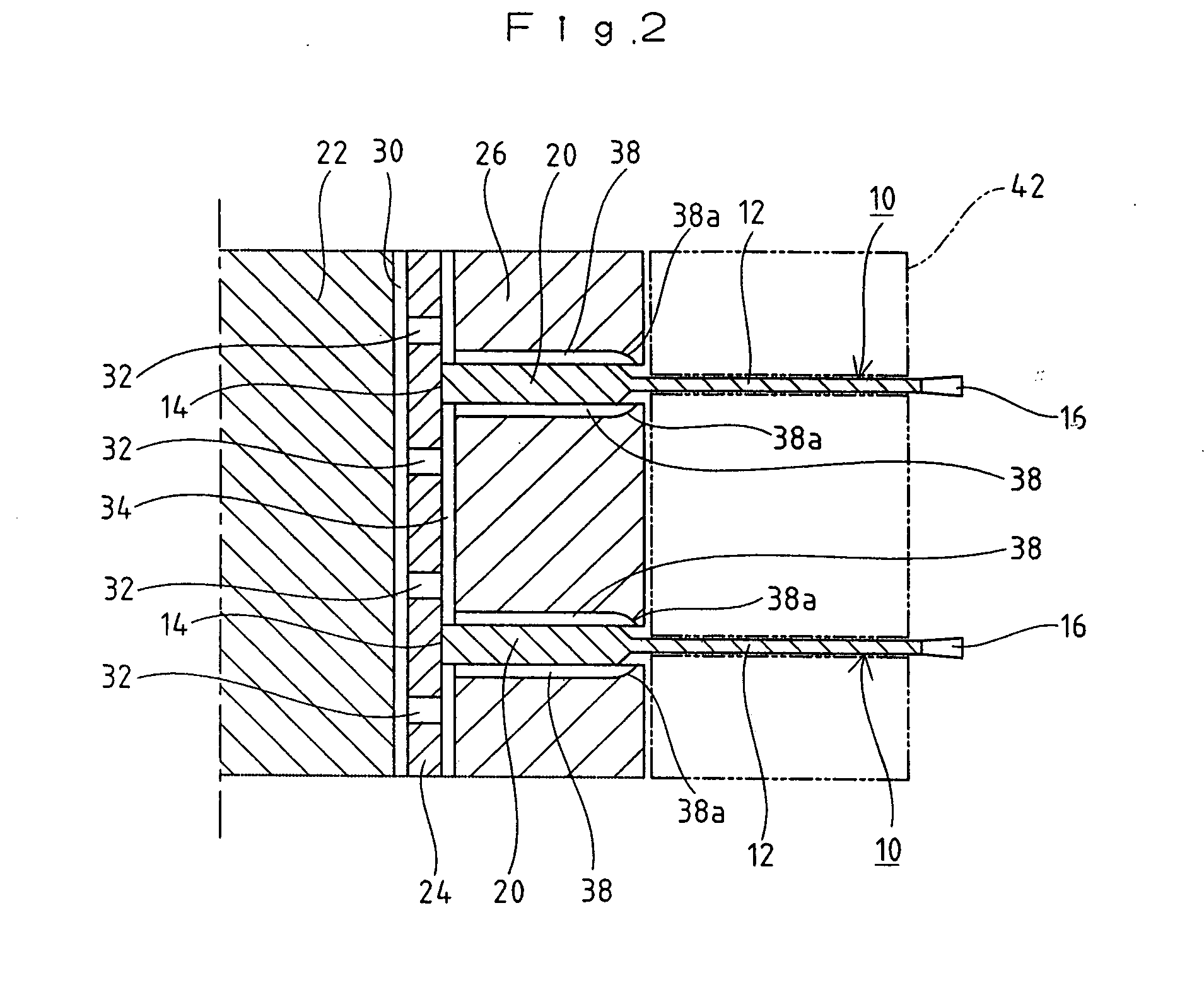
[0040]FIG. 1 is a cross-sectional half plan view of a fluid supply mechanism according to a first embodiment, and FIG. 2 is a vertically-sectional half side view of the fluid supply mechanism. The diameter of a shim 26 in this embodiment is set slightly larger than that of the boss 20 of the circular saw blade 10. Then, terminal ends 38a formed outwards in radial direction on the gutters 38 which are provided on both faces of the shim 26 are positioned at a near side of the outer peripheral edge of the shim 26 and beyond the outer diameter of the boss 20 of the circular saw blade 10. That is, the terminal ends 38a of each gutter 38 do not open beyond the outer periphery of the shim 26 but open beyond the outer diameter of the boss 20 of the circular saw blade 10. Also, the terminal ends 38a of the gutters 38 are obliquely curved so that the terminal ends 38a are directed to the base 12 of the circular saw blade 10 when the circular saw blade 10 are clamped and fixed by the shims 26 ...

second embodiment

[0042]FIG. 3 is a cross-sectional half plan view of the fluid supply mechanism according to a second embodiment, and FIG. 4 is a vertically-sectional half side view of the fluid supply mechanism. The diameter of a shim 26 in this embodiment is set approximately equal to or slightly smaller than that of the boss 20 of the circular saw blade 10. Furthermore, notches 44 recessed in the radial direction are provided on the outer periphery of the thick boss 20 at positions corresponding to the terminal ends 38a of the gutters 38. Then, the terminal ends 38a formed outwards in radial direction on the gutters 38 which are provided on both faces of the shim 26 are positioned at a near side of the outer peripheral edge of the shim 26. That is, the terminal ends 38a of each gutter 38 do not open beyond the outer periphery of the shim 26 but open at the positions of the notches 44 provided on the outer periphery of the boss 20 of the circular saw blade 10. Also, the terminal ends 38a of the gu...

third embodiment

[0043]FIG. 5 is a cross-sectional half plan view of a fluid supply mechanism according to a third embodiment, and FIG. 6 is a vertically-sectional half side view of the fluid supply mechanism. In this embodiment, the relationship in size between the shim 26 and the boss 20 of the circular saw blade 10 and the shape of the gutters 38 formed on the shim 26 are the same as those in the second embodiment. However, the notches 44 shown in the second embodiment are not formed on the boss 20.

[0044]Further, slits 46 extending by a required length outwards in the radial direction from origins positioned slightly inside the outer periphery of the boss 20 are formed in the base 12 of the circular saw blade 10 so as to pass through the base 12. The number of slits 46 corresponds to the number of gutters 38 formed on the shim 26, and in this embodiment, it is six. Then, the terminal ends 38a of the gutters 38 on the shim 26 are correspondingly positioned at origins (initial ends) of the slits 46...


PUM

PropertyMeasurementUnit
Lengthaaaaaaaaaa
Pressureaaaaaaaaaa
Diameteraaaaaaaaaa

Abstract

There is provided a fluid supply mechanism that, when a circular saw blade having a thick boss type base is used, can achieve lubrication and/or cooling of the circular saw blade by performing excellent mist supply.
The fluid supply mechanism includes a sleeve 24 with a required length that is attached to a rotary shaft 22, a required number of doughnut-like shims 26 attached to the sleeve 24 and a rotary tool 10 which is attached to the sleeve 24 and is clamped and fixed by the shims 26 from both sides. A fluid is transferred by pressure from gutter-like passages 30 formed on an inner periphery of the sleeve 24 via through holes 32 formed in the sleeve 24 in the radial direction, the fluid is transferred by pressure to passages 34 provided on inner peripheral faces of the shims 26 and gutters 38 formed to extend in the radial direction on both sides or one sides of the shims 26, and the fluid is supplied to the rotary tool 10 to lubricate and/or cool the rotary tool 10 during machining a work.

Description

TECHNICAL FIELD[0001]The present invention relates to a fluid supply mechanism for a rotary tool. In particular, the present invention relates to a fluid supply mechanism that (1) can adequately supply a fluid, such as lubricant, during machining a work and that (2) can successfully cool and / or lubricate the rotary tool, even if the thickness of a boss of the rotary tool attached to a cutting equipment is larger than that of a base provided with teeth along an outer periphery thereof.BACKGROUND ART[0002]A rotary tool, such as a circular saw blade, is attached to a rotary shaft of a circular sawing machine and rotated at high speed. However, there is the disadvantage that the temperature of the rotary tool rises abnormally due to friction during cutting a work, and a base or teeth thereof are broken or distorted to reduce its life. Therefore, during machining a work, a fluid, such as lubricant or water, is supplied to the rotary tool to lubricate and / or cool the same. When the fluid ...

Claims


Application Information

Patent Timeline
IPC IPC(8): B23D59/02
CPCB23D59/025Y10T83/263
Inventor IDE, TSUYOSHINISHIKAWA, YUKIOMITAKEYAMA, KENNAKANO, TAKAO
Owner KANEFUSA HAMONO KOUGIYOU KK
Why Eureka
Try Eureka