Fluid injector with rate shaping capability

a technology of injectors and fuel injection, applied in the direction of liquid fuel feeders, machines/engines, mechanical equipment, etc., can solve the problems of difficult to achieve the expansion of the capability range of common rail fuel injectors, and the inability to maximize the flexibility of injection characteristics

Inactive Publication Date: 2011-03-03
CATERPILLAR INC
View PDF37 Cites 23 Cited by
  • Summary
  • Abstract
  • Description
  • Claims
  • Application Information

AI Technical Summary

Benefits of technology

[0007]In another aspect, a method of controlling a speed of a check in a fluid injector includes a step of providing a fluid injector having a cavity wherein said cavity includes an upper surface and a lower surface. A check speed control device having an upper surface, lower surface, and orifice, positioned within the cavity is also provided. The space between the upper surface of the check speed control device and the upper surface of the cavity defines a first check control chamber, and the space between the lower surface of the check speed control device and the lower surface of the cavity defines a second check control chamber. The first check control chamber and second check control chamber are fluidly connected to one another via the orifice. The check speed control device is movable within the cavity between a first speed control position wherein at least a portion of the upper surface of the check speed ...

Problems solved by technology

Although these common rail fuel injection systems have many desirable aspects, the ability to maximize flexibility in injection charac...

Method used


Image

  • Fluid injector with rate shaping capability
  • Fluid injector with rate shaping capability
  • Fluid injector with rate shaping capability

Examples


Embodiment Construction

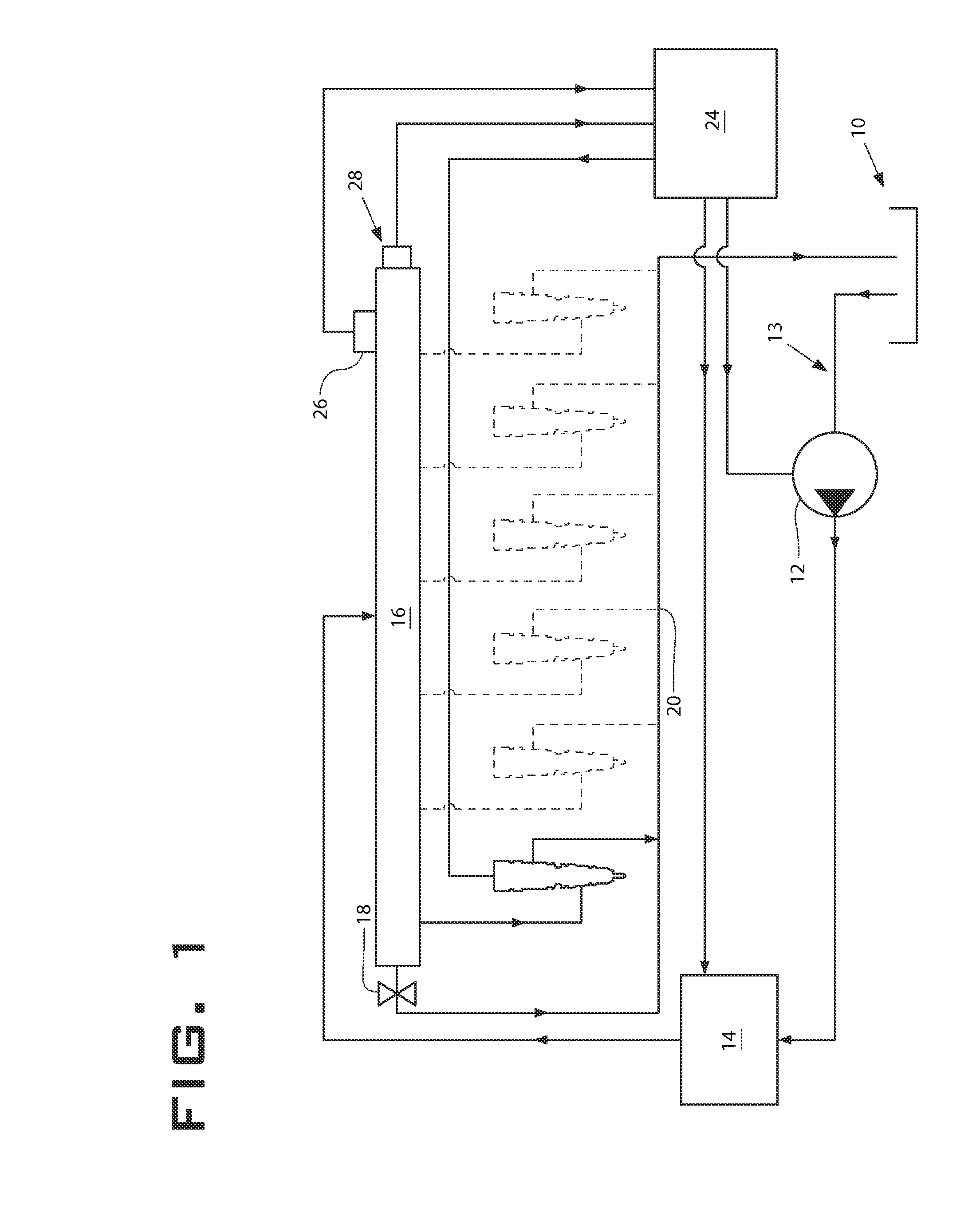
[0017]Referring to FIG. 1, a fuel system utilizing a common rail fuel injector 22 is shown. A reservoir 10 contains fuel at an ambient pressure. A transfer pump 12 draws low-pressure fuel through fuel supply line 13 and provides it to high-pressure pump 14. High-pressure pump 14 then pressurizes the fuel to desired fuel injection pressure levels and delivers the fuel to the fuel rail 16. The pressure in fuel rail 16 is controlled in part by safety valve 18, which spills fuel to the fuel return line 20 if the pressure in the rail 16 is above a desired pressure. The fuel return line 20 returns fuel to low-pressure reservoir 10.

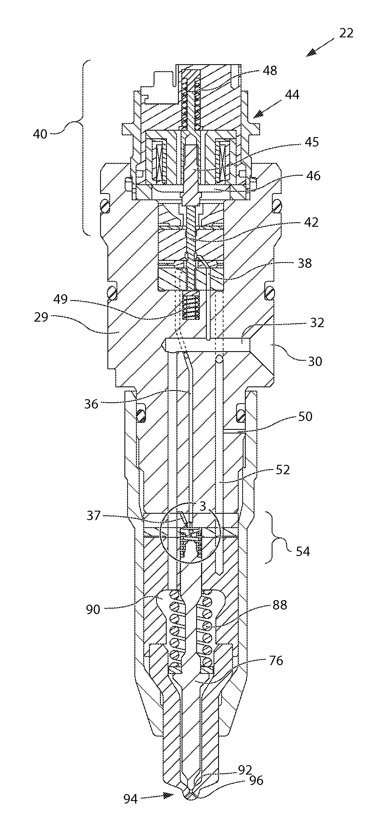
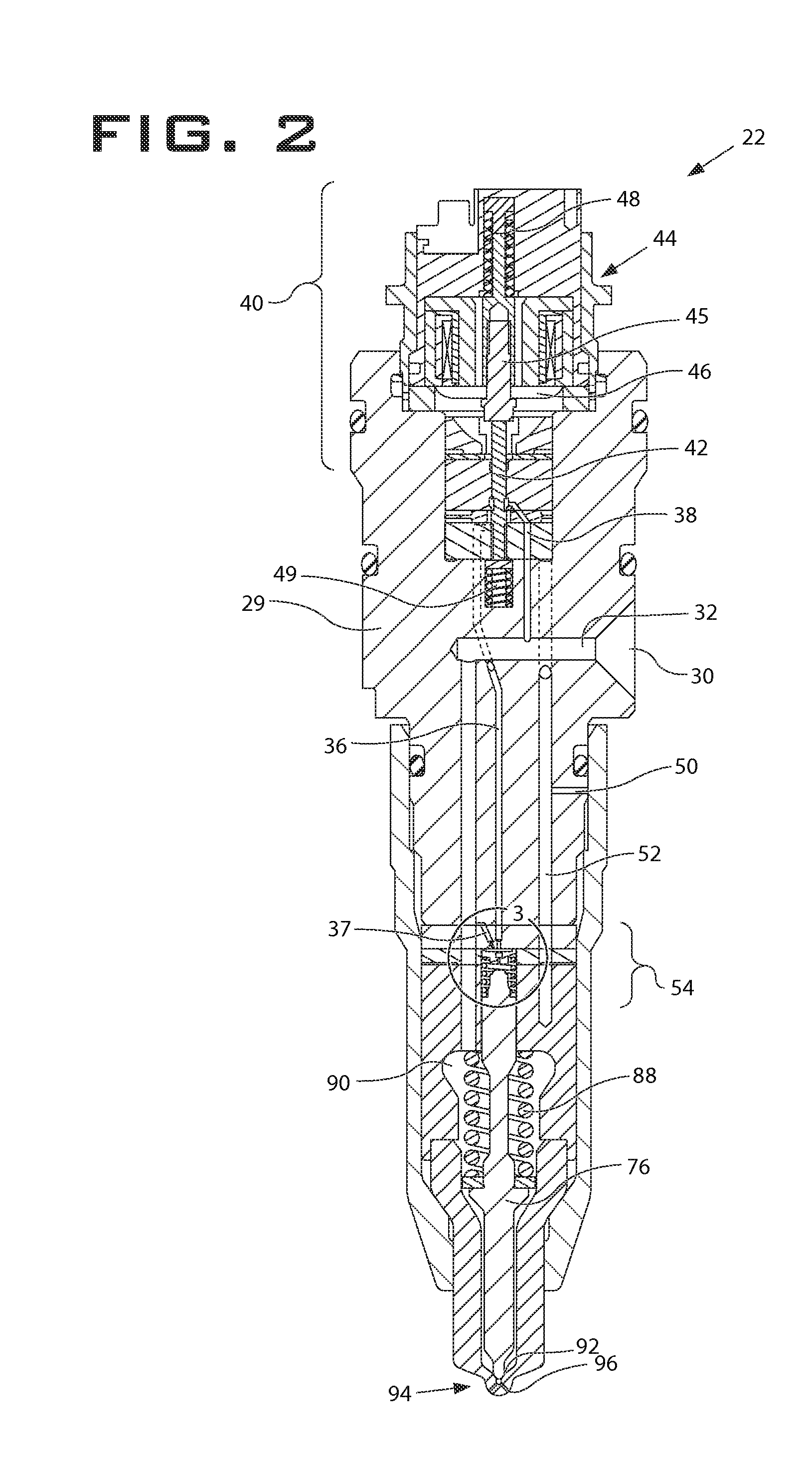
[0018]Fuel injector 22 draws fuel from rail 16 and injects it into a combustion cylinder of the engine (not shown). Fuel not injected by injector 22 is spilled to fuel return line 20. Electronic Control Module (ECM) 24 provides general control for the system. ECM 24 receives various input signals, such as from pressure sensor 26 and a temperature sensor 28 conne...


PUM


Abstract

A common rail single fluid injection system includes fuel injectors with one or two control valve assemblies with the ability to produce ramp, square and split injection rate shapes. This is accomplished by including a check speed control device disposed between a first and second check control chamber within a cavity defined by the injector body. The control valves and check speed control device control the speed of a check by controlling the flow of fuel out of the first and second check control chambers.

Description

TECHNICAL FIELD[0001]The present disclosure relates generally to a single fluid fuel injection system, and more particularly to fuel injection systems with rate shaping capabilities.BACKGROUND[0002]Engines, including diesel engines, gasoline engines, natural gas engines, and other engines known in the art, exhaust a complex mixture of combustion related constituents. The constituents may be gaseous and solid material, which include nitrous oxides (NOx) and particulate matter. Due to increased attention on the environment, exhaust emission standards have become more stringent and the amount of NOx and particulate matter emitted from an engine may be regulated depending on the type of engine, size of engine, and / or class of engine.[0003]Engineers have come to recognize that undesirable engine emissions, such as NOx, particulate matter, and unburnt hydrocarbons, can be reduced across an engine's operating range with fuel injection systems with maximum flexibility in controlling injecti...

Claims


Application Information

Patent Timeline
IPC IPC(8): F02M69/46F02M41/16
CPCF02M47/027F02M63/0063F02M63/0015
Inventor SOMMARS, MARK F.KIM, HOISANGIBSON, DENNIS
Owner CATERPILLAR INC
Why Eureka
Try Eureka