Photovoltaic Roofing Elements

a technology of photovoltaic roofs and components, applied in the direction of pv power plants, heat collector mounting/support, light and heating apparatus, etc., can solve the problems of inability to meet the needs of construction, so as to improve the understanding of embodiments

Active Publication Date: 2011-03-03
CERTAIN TEED LLC
View PDF31 Cites 71 Cited by
  • Summary
  • Abstract
  • Description
  • Claims
  • Application Information

AI Technical Summary

Benefits of technology

[0026]The invention will be further described with reference to embodiments depicted the appended figures. It will be appreciated that elements in the figures are illustrated for simplicity and clarity and have no

Problems solved by technology

First, fossil fuels have become increasingly expensive due to increasing scarcity and unrest in areas rich in petroleum deposits.
Second, there exists overwhelming concern about the effects of the combustion of fossil fuels on the environment due to factors such as air pollution (from NOx, hydrocarbons and ozone) and global warming (from CO2).
The interface between such connectors can be susceptible to ingress of moisture.
In some cases, bulky connectors with safety locks may be required depending on the accessibility of the electrical connection.
There exist low-profile connectors, but even these can be difficult to integrate with thin roofing products like asphalt or bituminous roofing shingles.
When such a low profile connector is used, useful connectors are often still quite bulky w

Method used


Image

  • Photovoltaic Roofing Elements
  • Photovoltaic Roofing Elements
  • Photovoltaic Roofing Elements

Examples


Embodiment Construction

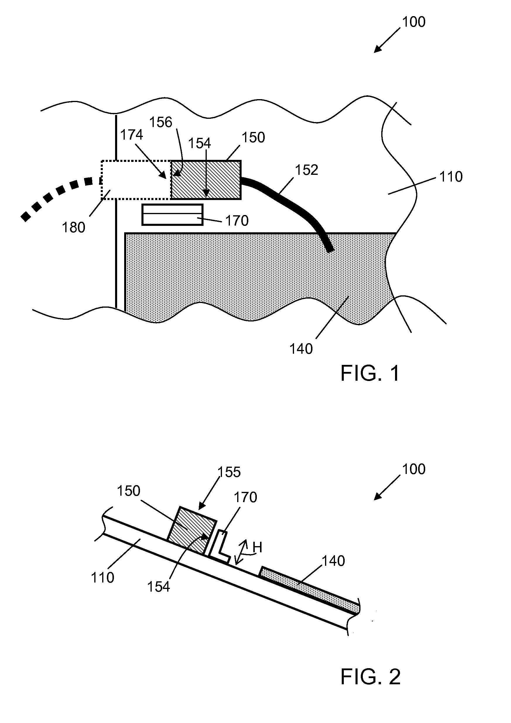
[0059]One aspect of the invention is a photovoltaic roofing element comprising a roofing substrate; a photovoltaic element disposed on the roofing substrate; an electrical connector operatively connected to the photovoltaic element, the electrical connector having a top side, a down-roof side and an electrical terminus; and a shield disposed adjacent the electrical terminus of the electrical connector on its down-roof side, its top side, or both. For example, in certain embodiments, the shield is disposed adjacent the electrical terminus of the electrical connector at least on its down-roof side. In other embodiments, the shield is disposed adjacent the electrical terminus of the electrical connector at least on its top side. As described in more detail below, the shield can be provided as part of the electrical connector, part of the roofing element, or as a separate piece assembled therewith.

[0060]One embodiment of the invention is shown in partial top schematic view in FIG. 1, an...


PUM

PropertyMeasurementUnit
Thicknessaaaaaaaaaa
Flexibilityaaaaaaaaaa
Energyaaaaaaaaaa

Abstract

The present invention relates generally to the photovoltaic generation of electrical energy. The present invention relates more particularly to photovoltaic roofing products for use in photovoltaically generating electrical energy. One aspect of the invention is a photovoltaic roofing element including a roofing substrate; a photovoltaic element disposed on the roofing substrate; an electrical connector operatively connected to the photovoltaic element, the electrical connector having a top side, a down-roof side and an electrical terminus; and a shield disposed adjacent the electrical terminus of the electrical connector on its down-roof side, its top side, or both.

Description

CROSS-REFERENCE TO RELATED APPLICATIONS[0001]This application claims priority under 35 U.S.C. §119(e) to U.S. Provisional Patent Application Ser. No. 61 / 238,566, filed Aug. 31, 2009, which is hereby incorporated herein by reference in its entirety.BACKGROUND OF THE INVENTION[0002]1. Field of the Invention[0003]The present invention relates generally to the photovoltaic generation of electrical energy. The present invention relates more particularly to photovoltaic roofing products for use in photovoltaically generating electrical energy.[0004]2. Technical Background[0005]The search for alternative sources of energy has been motivated by at least two factors. First, fossil fuels have become increasingly expensive due to increasing scarcity and unrest in areas rich in petroleum deposits. Second, there exists overwhelming concern about the effects of the combustion of fossil fuels on the environment due to factors such as air pollution (from NOx, hydrocarbons and ozone) and global warm...

Claims


Application Information

Patent Timeline
IPC IPC(8): H01L31/048H01L31/18E04D13/18
CPCY02B10/12Y02B10/20F24J2/5245Y10T29/49355H02S20/23H02S20/25H02S40/34H01L31/0483F24S25/61Y02B10/10Y02E10/47Y02E10/50H01L31/048
Inventor LIVSEY, ROBERT D.JENKINS, ROBERT L.JACOBS, GREGORY F.
Owner CERTAIN TEED LLC
Why Eureka
Try Eureka