[0008]In accordance with the present disclosure, a standard heavy-duty transport vehicle therefore is used, as it is employed already in a large number by the users of cranes for moving heavy loads, such as bridge elements or parts of oil rigs. Such heavy-duty transport vehicles have a separate drive and a separate drive controller. Since the driving forces of a heavy-duty transport device or a heavy-duty transport vehicle are relatively high, a high lateral force can be introduced to the crane when rotating the crane. This high lateral force is transmitted to the derrick boom, at whose head piece the derrick ballast is suspended. However, since a derrick boom basically represents a pressure rod, it is extremely sensitive to lateral forces. In accordance with the present disclosure, the drive controller of the heavy-duty transport device therefore is formed such that it can be influenced as a result of the movement of the crane.
[0009]Due to this influence, the drive controller of the heavy-duty transport device in accordance with one embodiment can be configured such that when rotating the crane it automatically determines the corresponding steering center and in
towing operation behind the crane steers, accelerates or decelerates automatically. As another example, the drive controller of the heavy-duty transport device may adjust operation of the heavy-duty transport drive in response to movement of the crane, such as in response to a length of the
variable length coupling element.
[0010]Even if in another variant the drive controller of the ballast carriage has not been upgraded such that it can automatically perform the aforementioned controls, the fact that the drive controller can be influenced by the crane movement in accordance with the present teaching ensures that for the case that a steering error of the heavy-duty transport device leads to an undesired introduction of force into the coupling element between the uppercarriage and the ballast carriage the separate drive of the heavy-duty transport device stops the entire
system, i.e. both the crane and the heavy-duty transport device, so that for example by manual control the ballast carriage can again by moved into the desired position by means of its own drive. Subsequently, operation of the crane can again be continued.
[0021]Further features, details and advantages of the present disclosure will be explained in detail below with reference to embodiments illustrated in the drawing, in which:
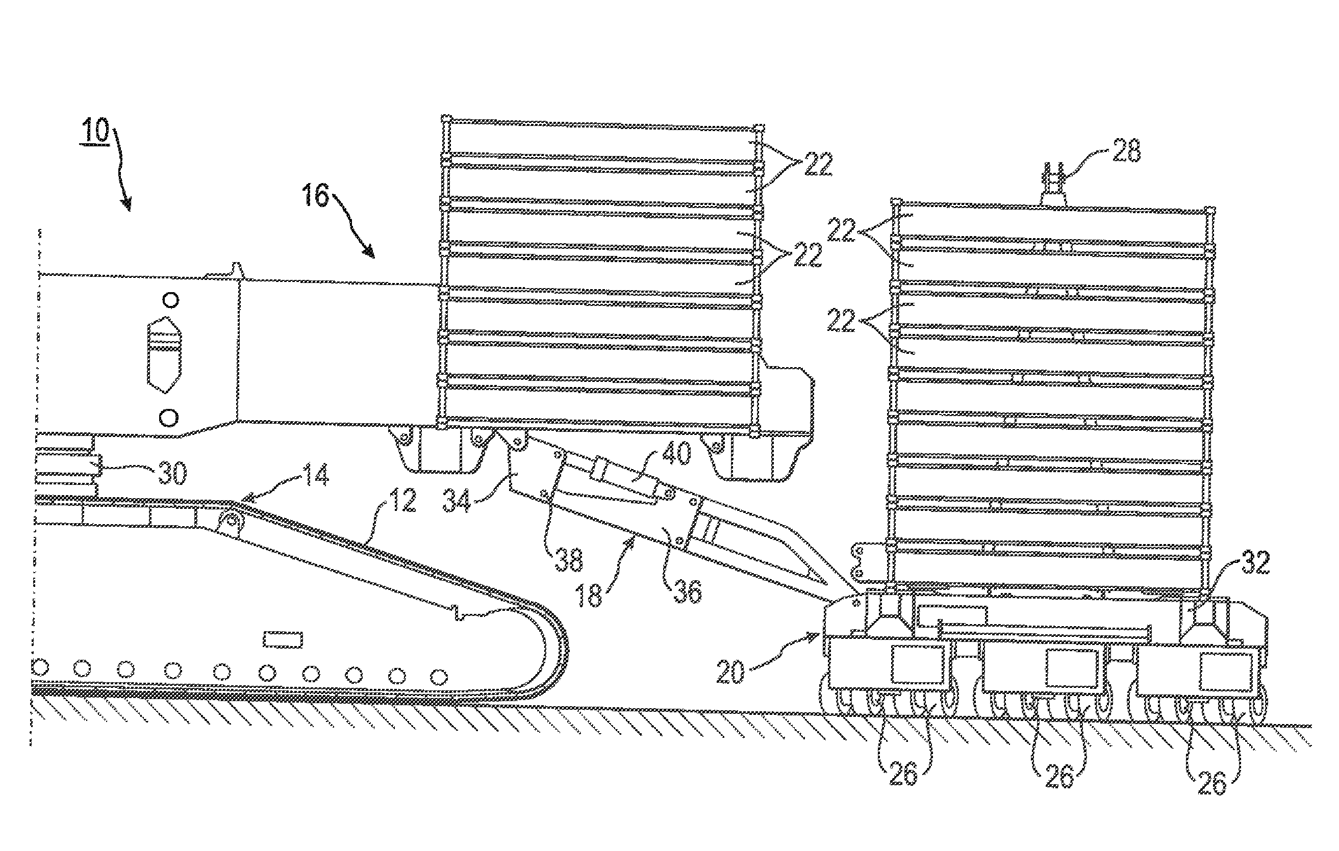
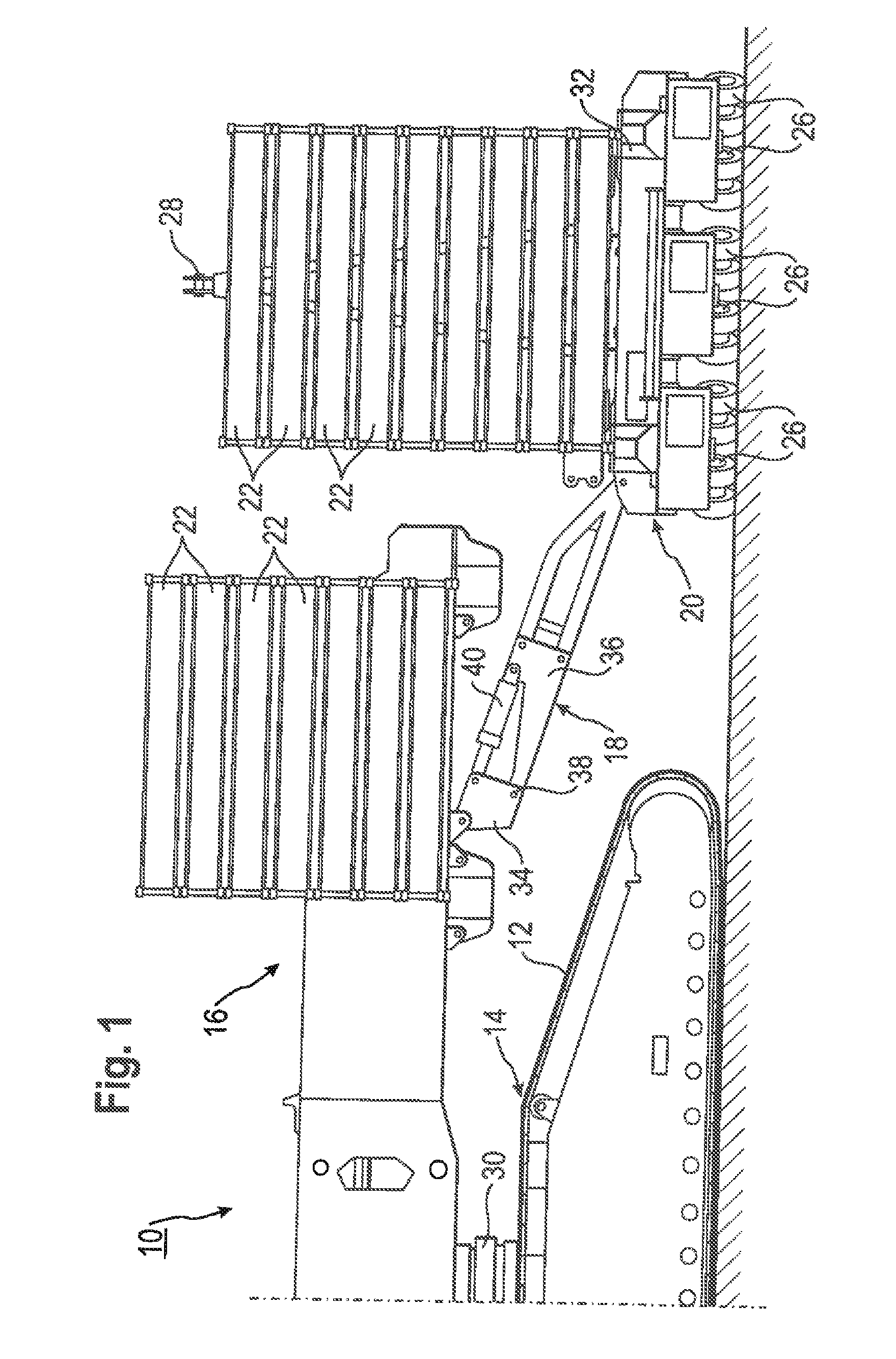
[0012]The coupling element between the uppercarriage and the ballast carriage can be designed to be variable in its length and can include a length sensor. The coupling element advantageously can consist of two articulated rods which are coupled via a
hydraulic cylinder acting as length sensor. The length of the
hydraulic cylinder now is monitored via a corresponding sensor communicating with one or more of the drive controllers. Each change in
stroke of the
hydraulic cylinder is detected and converted into an actuation
signal, which can be used for correction of the steering error or for switching off. In
towing operation behind the crane, the ballast carriage can be accelerated, decelerated or also stopped, depending on the deflection of the
piston in the hydraulic cylinder.
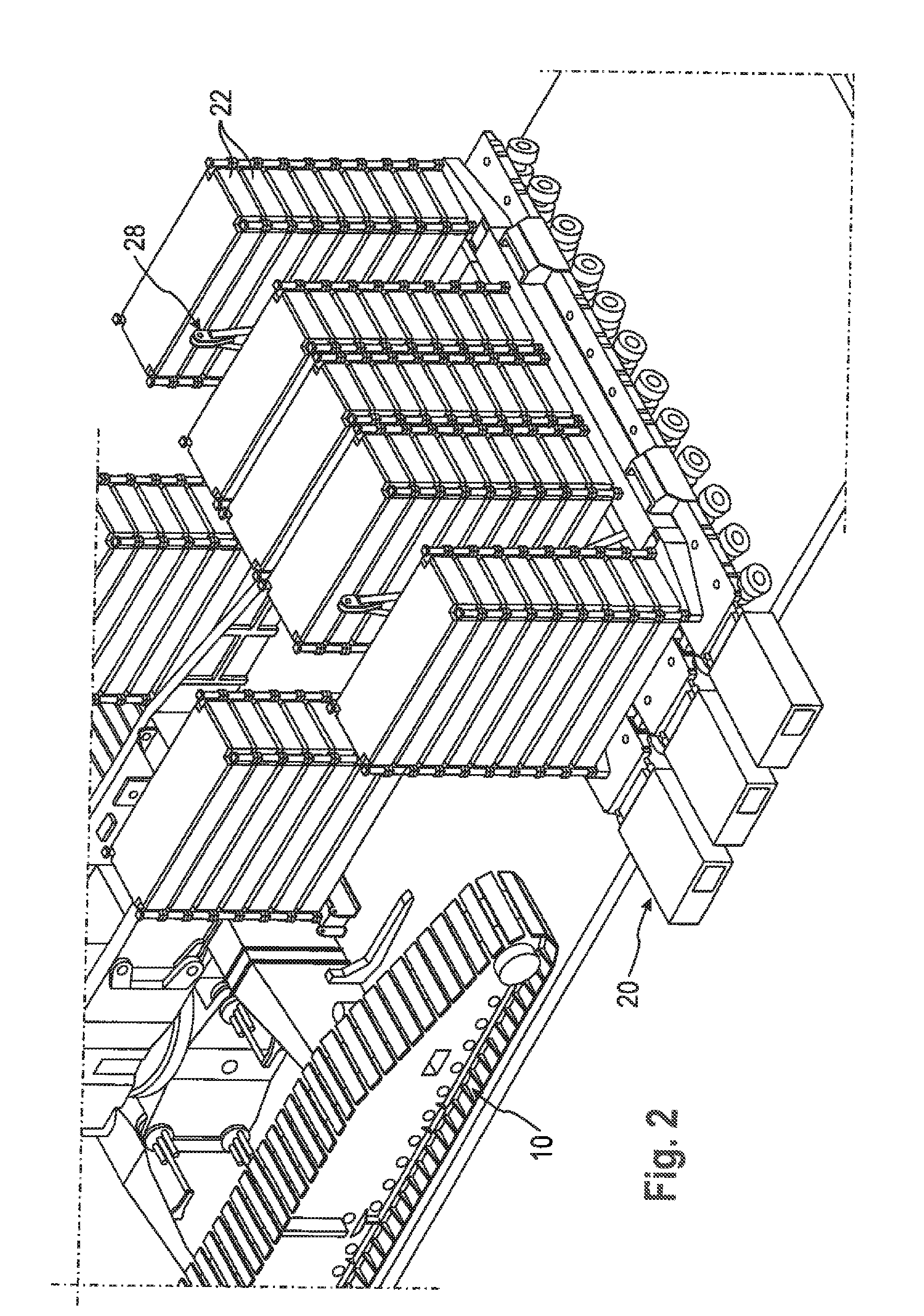
[0013]In accordance with another preferred aspect of the present disclosure, the ballast is placed on a
pallet which can be mounted on the heavy-duty transport device and be connected with the same. In this way, a heavy-duty transport device already present with the user can be employed as ballast carriage in a particularly easy way. It must only be ensured that the corresponding
pallet is connected with the heavy-duty transport vehicle after being mounted correspondingly.
[0017]In accordance with an advantageous development of the above-described preferred variant, the relative longitudinal movement is realized by a longitudinal guide with a pivot pin such that both a longitudinal movement and a rotary movement is permitted, whereas no movement is permitted in transverse direction. By restricting the movement in transverse direction it is prevented that undesired lateral forces are transmitted to the derrick boom.
[0018]In accordance with a further development of this variant, it should be noted that the
pallet hangs on pendulums consisting of rods, which at their upper end are articulated to the rigid guide frame and at their lower end to the pallet directly or indirectly via spherical plain bearings. To avoid a too much inclined position of the heavy-duty transport device and in particular of the ballast piled up on the same during a possible relative movement between crane and heavy-duty transport device, the pendular movement can be limited by emergency stops to be provided correspondingly.
[0019]Quite particularly advantageously, the pendular movement can be detectable via measuring means, preferably angle sensors, such that due to the measured variables detected actuation signals can be generated for the drive controller.

