Base for pressurized bottles

US20110049083A1Inactive Publication Date: 2011-03-03AMCOR RIGID PLASTICS USA

Image

  • Base for pressurized bottles
  • Base for pressurized bottles
  • Base for pressurized bottles

Examples


Embodiment Construction

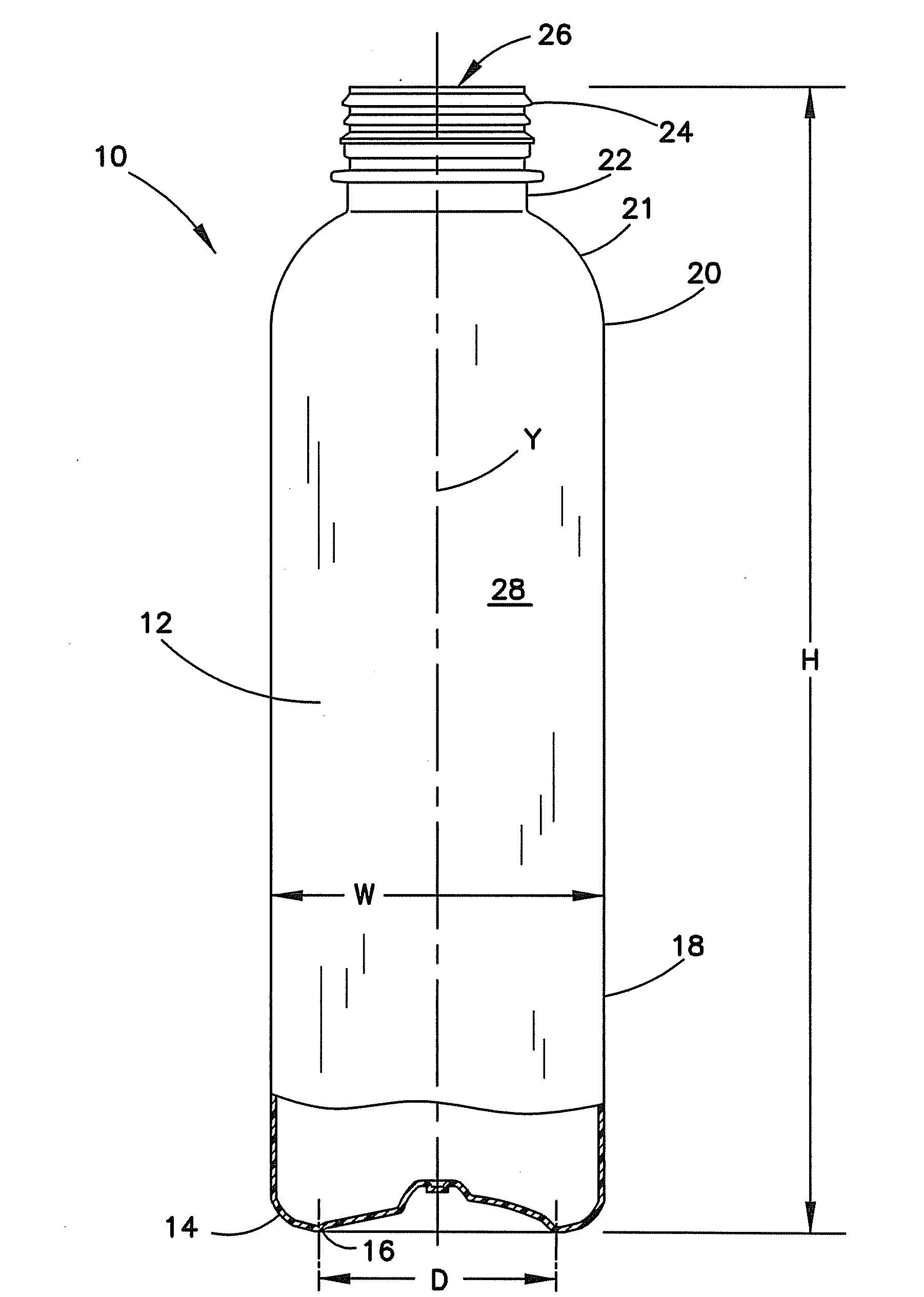
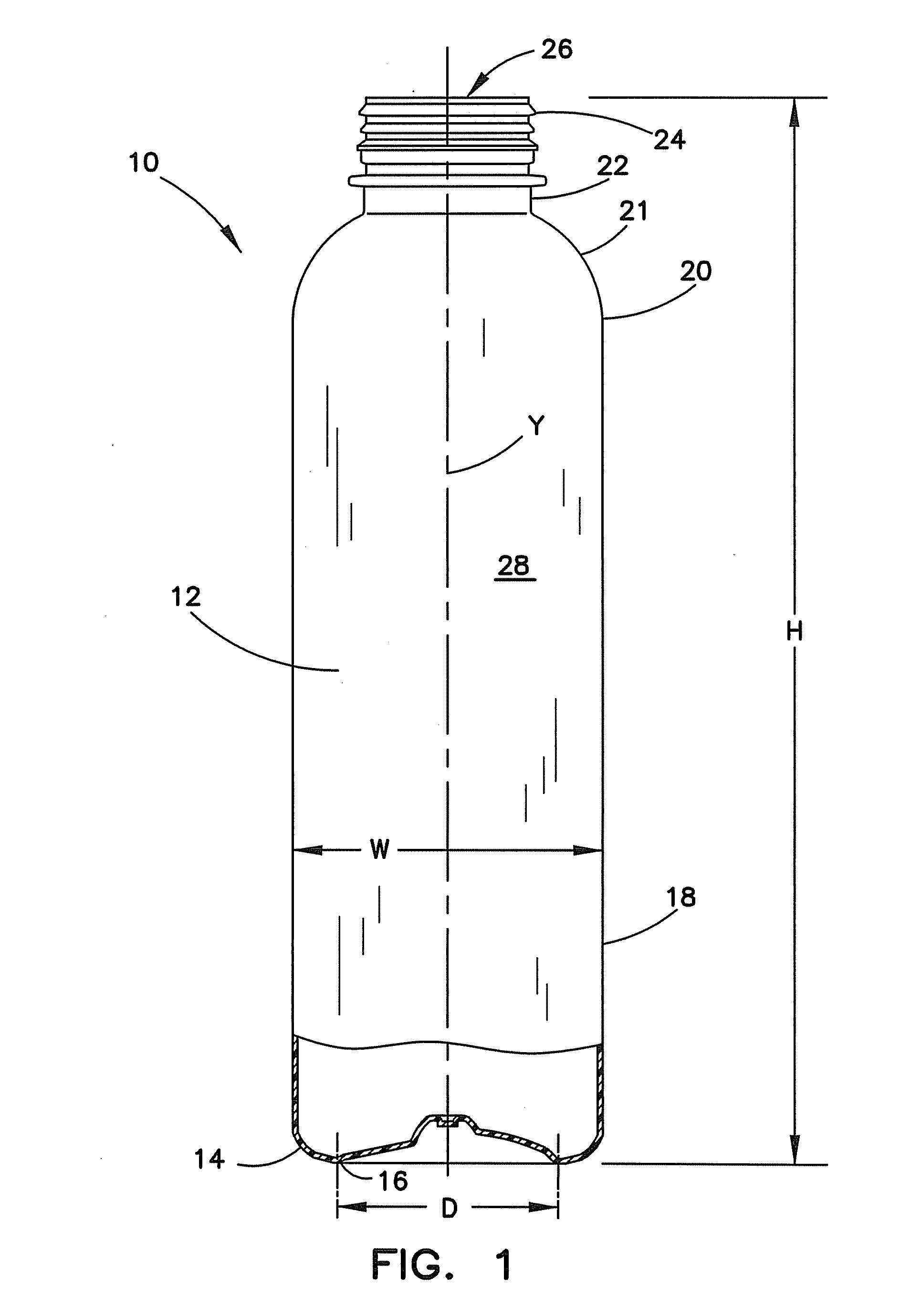
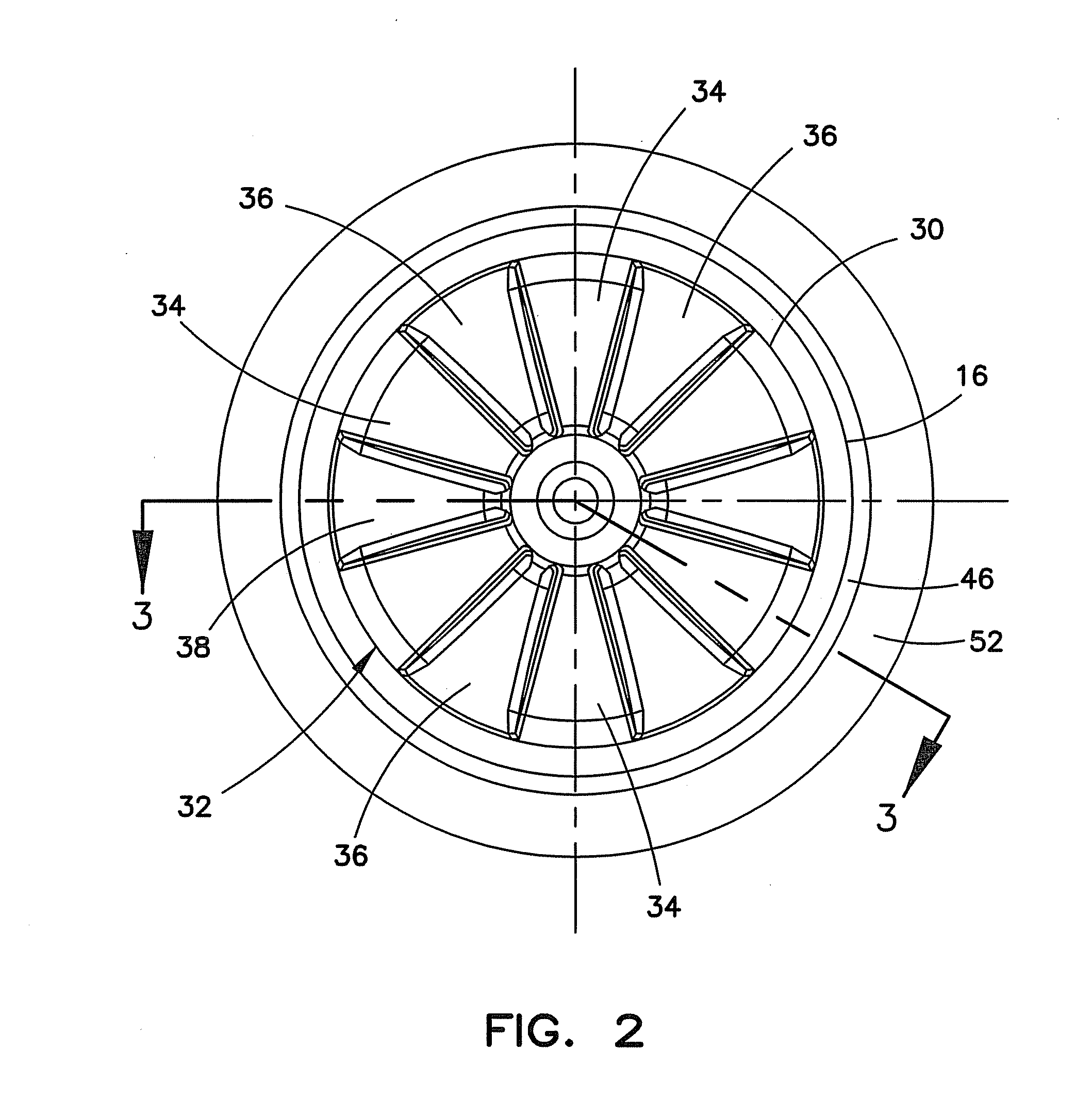
A bottle 10 is shown in FIG. 1 and the other Figs that has a generally cylindrical body 12 surrounding a longitudinal axis Y and a closed base 14 that is unitary with the remainder of the bottle. The 14 base has a continuous standing ring 16 to support the bottle 10 on any underlying support surface. The standing ring 16 has a standing ring diameter D. A side wall 18 is formed unitarily with the base 14 and extends from the base upward to an upper end 20 of the side wall 18. A neck 22 is unitarily connected to the upper end 20 of the side wall 18 by a shoulder portion 21. The neck 22 includes a finish 24 adapted to receive a cap (not shown) to close an opening 26 into the bottle interior 28. The bottle 10 has a height H defined by the distance between the opening 26 and the standing ring 16, and a maximum width W across the bottle 10.

To enhance the vertical alignment or perpendicularity of the bottle 10, the base standing ring 16 can be defined in vertical cross-section by a continu...


PUM


Abstract

A plastic bottle with a base centered on a vertical axis, a continuous standing ring to support the bottle, a side wall formed unitarily with the base extending from the base upward to an upper side wall end, and a neck connected to the side wall upper end, the neck including a finish adapted to receive a cap to close an opening into the bottle interior. The bottle base standing ring is defined in vertical cross-section by a continuous curve bounded on a radial inside by an interior region that can include a plurality of concave domed wedge-shaped sections interspaced with buttress sections having substantially planar inclined outer portions. The bottle base standing ring has a diameter less than 80% of the maximum side wall width and is bounded on a radial outside by a conic section portion centered on the vertical axis having an apex angle of less than 1600 to improve the perpendicularity of the bottle.

Description

BACKGROUNDThe present disclosure is directed to plastic bottles, and particularly to a supporting champagne style base that is unitary with the remainder of the bottle, which improves the perpendicularity of the bottle.Plastic bottles that include a base having a continuous uninterrupted standing ring for supporting the bottle on any underlying surface are sometimes referred to having a champagne style base. The perpendicularity or vertical alignment of such bottles can depend on the evenness of material distribution in the area of the standing ring, particularly when the bottles are subjected to even small internal pressures of 15 psi or less. While small variations from a true vertical alignment can be tolerated, any significant variation may cause problems in subsequent labeling and boxing of such bottles. While a large diameter standing ring is generally thought to provide enhanced stability as a result of the larger foot print, the large diameter standing ring is more flexible ...

Claims


Application Information

Patent Timeline
03 Mar 2011
Publication
US20110049083A1
IPC
B65D90/02
CPC
B65D1/0276
Inventors
SCOTT, ANTHONY J.; ROSS, JOHN R.