Control flows and forces in vtol vehicles

US20110049306A1Active Publication Date: 2011-03-03URBAN AERONAUTICS

Image

  • Control flows and forces in vtol vehicles
  • Control flows and forces in vtol vehicles
  • Control flows and forces in vtol vehicles

Examples


Embodiment Construction

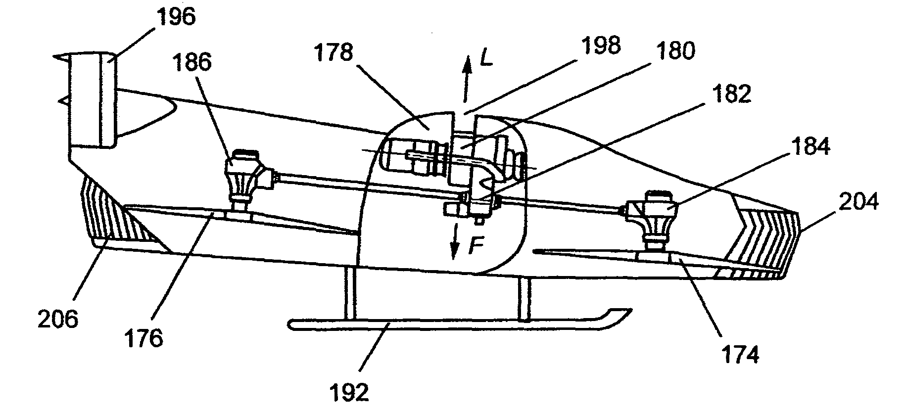
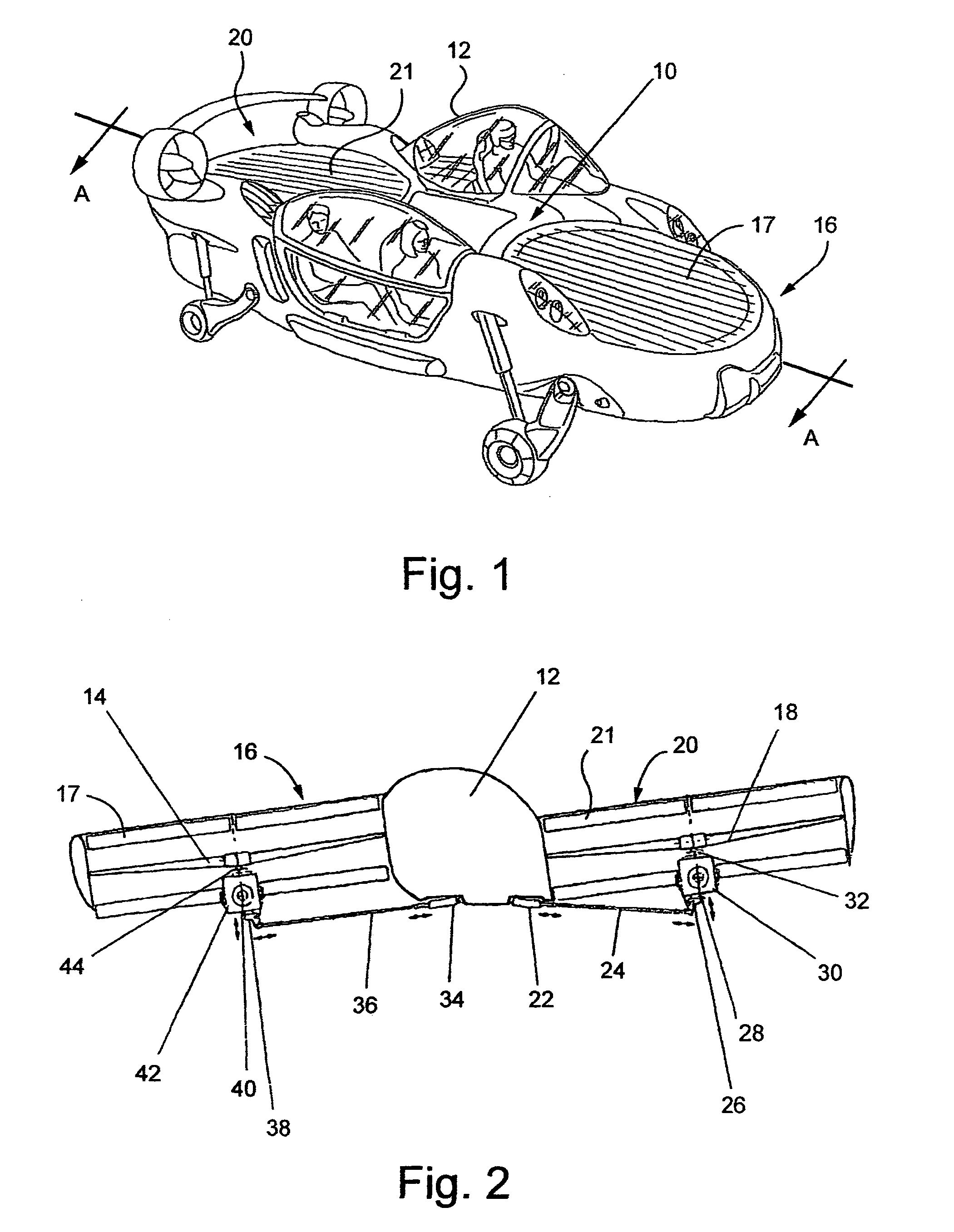
[0072]FIGS. 1 and 2 schematically illustrate one example of a ducted fan vehicle 10 having an optional compartment 12 (which may or may not be a pilot's cockpit) located between a forward lift producing propeller 14 in a forward duct 16 and an aft lift producing propeller 18 in an aft duct 20. Inlets to the ducts 16 and 20 are provided with adjustable control vanes 17 and 21, respectively, which extend substantially parallel to the longitudinal axis of the vehicle. At least one of the lift-producing propellers has variable pitch which is controlled by means such as, for example, an actuator 22 with its moving part connected to a rod (or shaft) 24 which is also linked to a bell crank 26, which is a mechanism that changes the direction of the movement by transforming the motion of the rod into a different motion at another point of the bell crank 26, which is in turn connected to a push pull rod 28. The push pull rod 28 moves through an opening in a transmission unit 30 (or by it) and...


PUM


Abstract

The present application relates to VTOL vehicles with multi-function capabilities and, specifically to ducted fan arrangements that facilitate the control of forces and flows of air to control movement of the vehicle in six degrees of freedom in both primary and secondary modes of operation. Also disclosed are pitch control mechanisms for the lift propellers of VTOL vehicles: drive and transmission arrangements; a specially configured exhaust duct for directing exhaust gases from such vehicles along an upper surface of the vehicle; and shock absorbing components for the landing gear of such vehicles.

Description

[0001]This application claims priority from U.S. Provisional Application Ser. No. 60 / 924,168, filed May 2, 2007,the entirety of which is incorporated herein by reference.FIELD AND BACKGROUND OF THE INVENTION[0002]The present application relates to VTOL vehicles with multi-function capabilities and, specifically to ducted fan arrangements that facilitate the control of forces and flows of air and control movement of the vehicle in six degrees of freedom. The invention also relates to pitch control mechanisms for the lift propellers of VTOL vehicles: drive and transmission arrangements; the control of exhaust gases from such vehicles; and shock absorbing characteristics in the landing gear of such vehicles.[0003]VTOL vehicles rely on direct thrust from propellers or rotors, directed downwardly, for obtaining lift necessary to support the vehicle in the air. Many different types of VTOL vehicles have been proposed where the weight of the vehicle in hover is carried directly by rotors o...

Claims


Application Information

Patent Timeline
03 Mar 2011
Publication
US20110049306A1
IPC
B64C29/00
CPC
B64C29/0025
Inventors
YOELI, RAPHAEL