
Methods for Laser Cutting Glass Substrates

a technology of laser cutting and glass substrate, which is applied in the direction of glass making apparatus, welding/soldering/cutting articles, manufacturing tools, etc., can solve the problems of difficult mechanically scribe glass substrate, difficult to cut and finish chemically strengthened glass substrate, and glass may break in an explosive manner

Inactive Publication Date: 2011-03-03
CORNING INC
View PDF100 Cites 129 Cited by
  • Summary
  • Abstract
  • Description
  • Claims
  • Application Information

AI Technical Summary

Benefits of technology

The patent describes methods for cutting glass articles from strengthened glass substrates with surface compression layers and tensile layers. The methods involve forming edge defects or scanning laser beams to create through vents that allow for precise cutting along a cut line. The technical effects of the patent include improved precision and efficiency in the cutting process, which can save time and reduce waste.

Problems solved by technology

The magnitude of compressive stress and the elastic energy stored within the central tension region may make cutting and finishing of chemically strengthened glass substrates difficult.
The high surface compression and deep compression layers make it difficult to mechanically scribe the glass substrate as in traditional scribe-and-bend processes.
Furthermore, if the stored elastic energy in the central tension region is sufficiently high, the glass may break in an explosive manner when the surface compression layer is penetrated.
In other instances, the release of the elastic energy may cause the break to deviate from a desired involve cutting and finishing the non-chemically strengthened glass to shape before the strengthening process.

Method used


Image

  • Methods for Laser Cutting Glass Substrates
  • Methods for Laser Cutting Glass Substrates
  • Methods for Laser Cutting Glass Substrates

Examples


Embodiment Construction

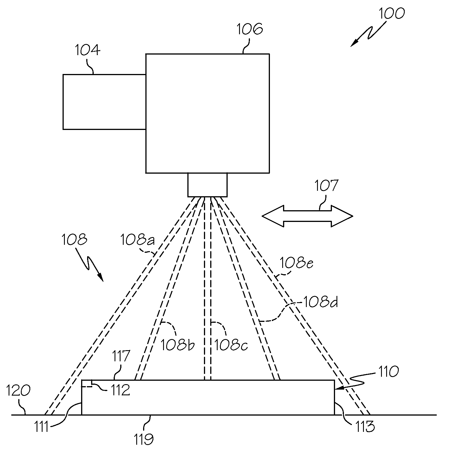
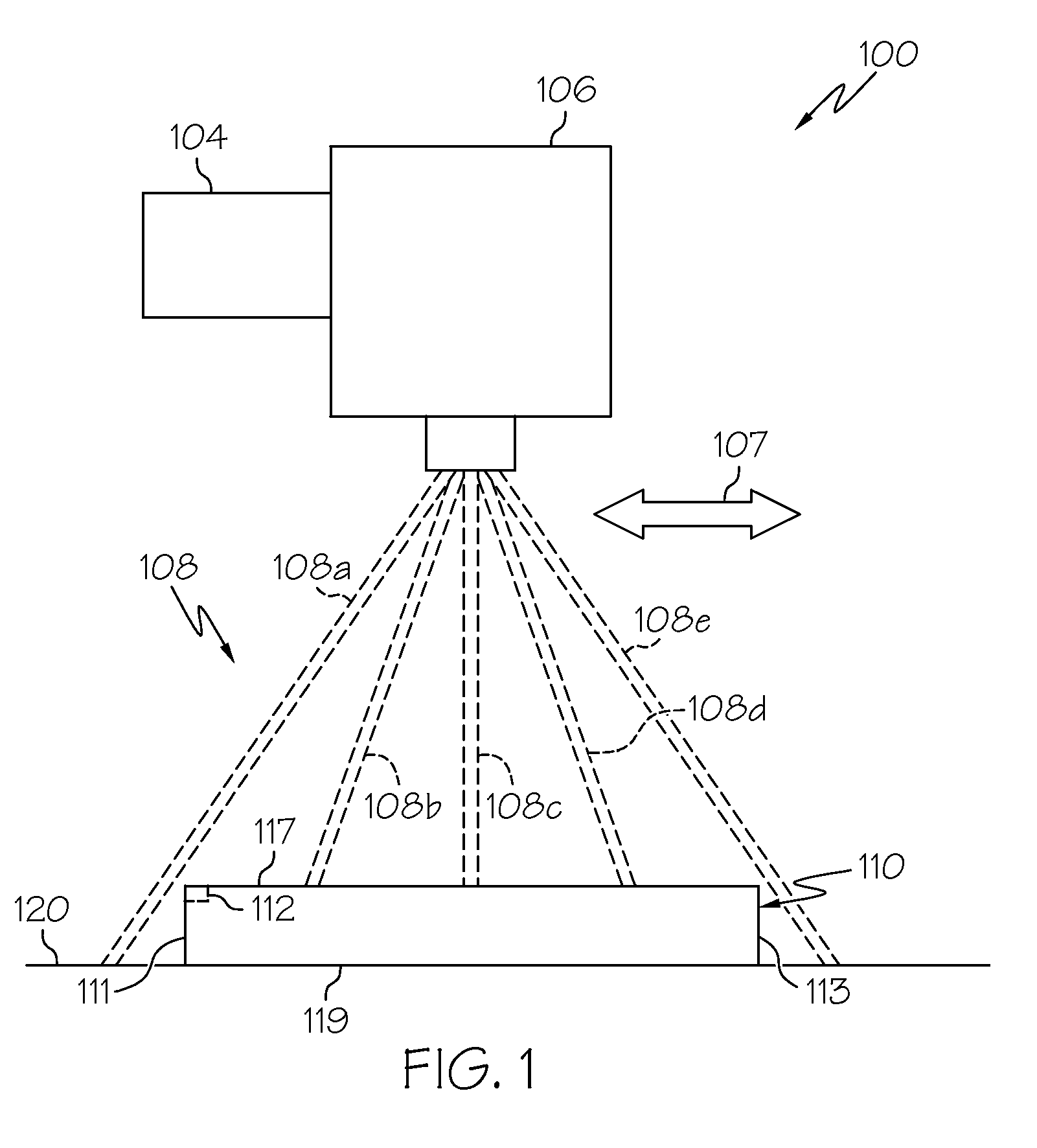
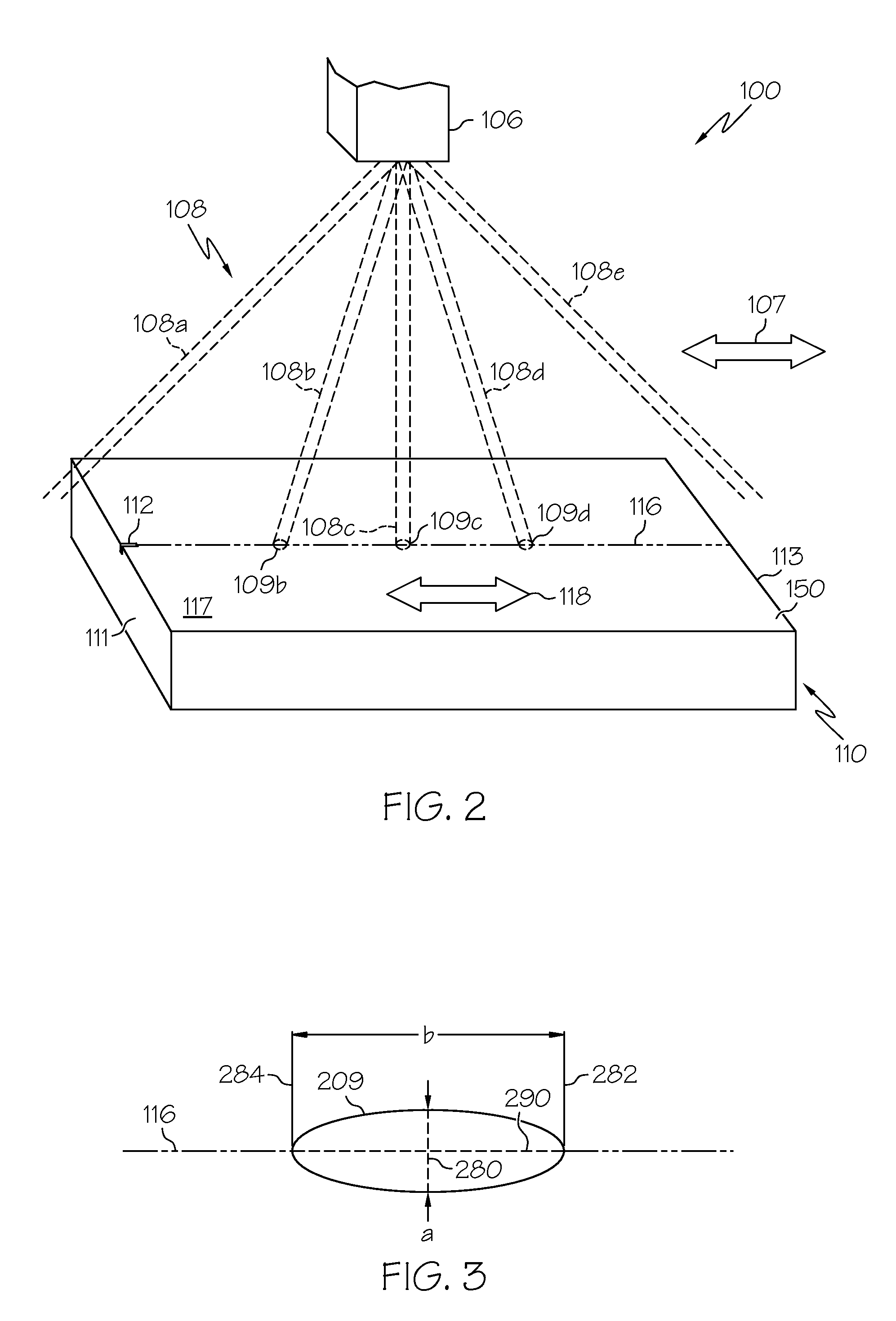
[0025]Reference will now be made in detail to various embodiments for cutting strengthened glass substrates, examples of which are illustrated in the accompanying drawings. Whenever possible, the same reference numerals will be used throughout the drawings to refer to the same or like parts. As described herein, methods for cutting glass articles from strengthened glass substrates generally comprise forming a defect on the strengthened glass substrate. The defect is positioned on a cut line that defines a region of separation. A laser beam is rapidly scanned along the entire length of the cut line and over the edge defect to initiate a through vent at the edge defect. The through vent travels completely through the glass substrate (i.e., between the top and bottom layers). The laser beam may be continuously scanned along the length of the cut line such that the through vent quickly propagates through the glass substrate along the scanned laser line to cut the glass article from the ...


PUM

PropertyMeasurementUnit
frequencyaaaaaaaaaa
depthsaaaaaaaaaa
compressive layeraaaaaaaaaa

Abstract

A method for cutting a glass article from a strengthened glass substrate having a surface compression layer and a tensile layer includes forming an edge defect in the surface compression layer on a first edge of the strengthened glass substrate. The method further includes propagating a through vent through the surface compression and tensile layers at the edge defect. The through vent precedes a region of separation along a cut line between the glass article and the strengthened glass substrate.

Description

CROSS-REFERENCE TO RELATED APPLICATIONS[0001]This application claims the benefit of priority under 35 U.S.C. §119(e) of U.S. Provisional Application Ser. No. 61 / 237,728 filed on Aug. 28, 2009.BACKGROUND[0002]1. Field[0003]The present specification generally relates to methods for cutting and separating glass substrates and, more specifically, to methods for laser cutting and separating strengthened glass substrates.[0004]2. Technical Background[0005]Thin strengthened glass substrates, such as chemically, thermally, or laminate strengthened substrates have found wide-spread application in consumer electronics because of their excellent strength and damage resistance. For example, such glass substrates may be used as cover sheets for LCD and LED displays and touch applications incorporated in mobile telephones, display devices such as televisions and computer monitors, and various other electronic devices. To reduce manufacturing costs it may be desirable that such glass substrates us...

Claims


Application Information

Patent Timeline
Patent Type & Authority Applications(United States)
IPC IPC(8): B29C35/08
CPCB23K26/4075B23K26/00C03C23/0025C03B33/093B23K26/40Y02P40/57B23K2103/50C03B33/0222C03B33/023C03B33/072C03B33/091
Inventor LI, XINGHUAMOORE, LISA ANNE
Owner CORNING INC
Learn More