
Food dicer

a technology of food dicers and dicers, which is applied in the field of food dicers, can solve the problems of time-consuming and laborious dicing, uneven lengths, and risks of cutting fingers, and achieve the effects of convenient cleaning, low manufacturing cost and convenient cleaning

Active Publication Date: 2009-05-14
TWEG EDWARD
View PDF4 Cites 23 Cited by
  • Summary
  • Abstract
  • Description
  • Claims
  • Application Information

AI Technical Summary

Benefits of technology

[0018]It is a further aim of the invention that the manual tool does not require any electrical power and cannot cause electrocution.
[0019]Furthermore, by being manual, the tool is relatively cheap to manufacture.
[0020]The device has a minimum number of parts and is easy to clean, and keep hygienic.
[0023]In one embodiment, the second upper surface of the cutting base of the dicing tool has a clasp attached thereto such that said clasp is positioned behind and beneath the handle of the cutting base and coupled thereto with a Hookian member; such that squeezing the clasp towards the handle brings the second section down towards the first section, and brings the V shaped horizontal cutting blade into alignment with the triangular shaped front edge of the first section, thereby resulting in the second section assuming its lower position; and releasing the clasp releases the potential energy stored in the Hookian member, causing Hookian member to expand and bring the second section to its upper position.

Problems solved by technology

Knives make one cut at a time, and manually dicing is time consuming, labor intensive and risks cutting fingers, particularly where occasional cooks attempt to dice foodstuffs.
Additionally any technique that relies on making one cut at a time, relying on the eye of the knife wielder to ensure that the foodstuff is cut into equal lengths, will invariable result in uneven lengths.
With one dimensional objects, this is not necessarily too bad, but where the foodstuff is to be diced into cubes, miscalculation of length leads to an unaesthetic result.
Although wires can be used for cutting cheese as well, an array of wires is really only useful for slicing eggs, soft cheeses, bananas and other foodstuffs of similar low resistance.
It cannot be used on firmer vegetables, such as potatoes, and cannot be used on soft-fruit or vegetables, such as tomatoes, for example.
Although a further guillotine blade could be added in front of the grid, at a fixed distance therefrom, to cut the extruded chips into cubes, such a guillotine blade would only make one cut at a time, and would be inherently dangerous.
Such a device would not be suitable for fresh summer fruits or for making an Israeli style, tomato and cucumber salad for example.
These are multi-purpose machines and are generally-sophisticated appliances which, apart from their high cost, often have the disadvantage of being inconvenient to use and also difficult to assemble and clean.
Since the food to be cut impacts the horizontal cutting blade head on, even where the blade is sharp, such a system, though no doubt ideal for cubing onions, the intended purpose thereof, is unable to slice ripe tomatoes without squashing them.
The device described does not appear to be able to chip or cube vegetables, merely to slice them.

Method used


Image

  • Food dicer
  • Food dicer
  • Food dicer

Examples


second embodiment

[0062]Referring now to FIGS. 5a to 5d, in a second embodiment, the cutting base 10′ has a clasp 60 attached to the second part 44′, at the bottom thereof, behind the handle 58. Pulling on clasp 60 brings the second part 44′ down into coalignment with the first part 40, bringing the V shaped horizontal cutting blade 48 behind the triangular shaped front edge of the first part 40, the second part 44′ assuming its lower position thereby, extending and storing energy in the Hookian member, typically helical spring 56′. Releasing clasp 60 allows spring 56′ to contract, bringing the second part 44′ up away from the first part 40 and bringing the V shaped horizontal cutting blade 46 into alignment with the apices of the triangular vertical cutting blades, the second part 44′ assuming its upper position thereby.

[0063]The embodiment of FIG. 5 may be used to dice food by the following method: (i) Bringing the second part 44′ into its lower position by gripping the clasp 60 with the fingers of...

third embodiment

[0065]The third embodiment may be used for dicing a foodstuff by the method of: (i) pulling lever 70, thereby pressing second part 44″ down with wheel 72, bringing the second part into its lower position; (ii) Sliding the foodstuff holder 14 along the cutting base 12″ and over the upper surface of the first 40 and second 44 parts, from the second part 44 onto the first part 40, across the triangular vertical blades 42a-j towards the handle 58, making a first plurality of regularly spaced, equidistant vertical cuts in the block of foodstuff thereby; (iii) Releasing lever 70, causing wheel 72 to retract and bringing the second section 44″ up away from the first section 40 thereby bringing the V shaped horizontal cutting blade 46 into alignment with the apices of the triangular vertical cutting blades 42a-j, the second section 44″ assuming its upper position thereby, and (iv) Drawing the block of foodstuff back over the cutting base 12″, across the triangular vertical blades 42a-j, mak...


PUM

PropertyMeasurementUnit
Angleaaaaaaaaaa
Potential energyaaaaaaaaaa

Abstract

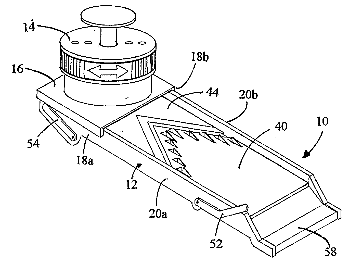
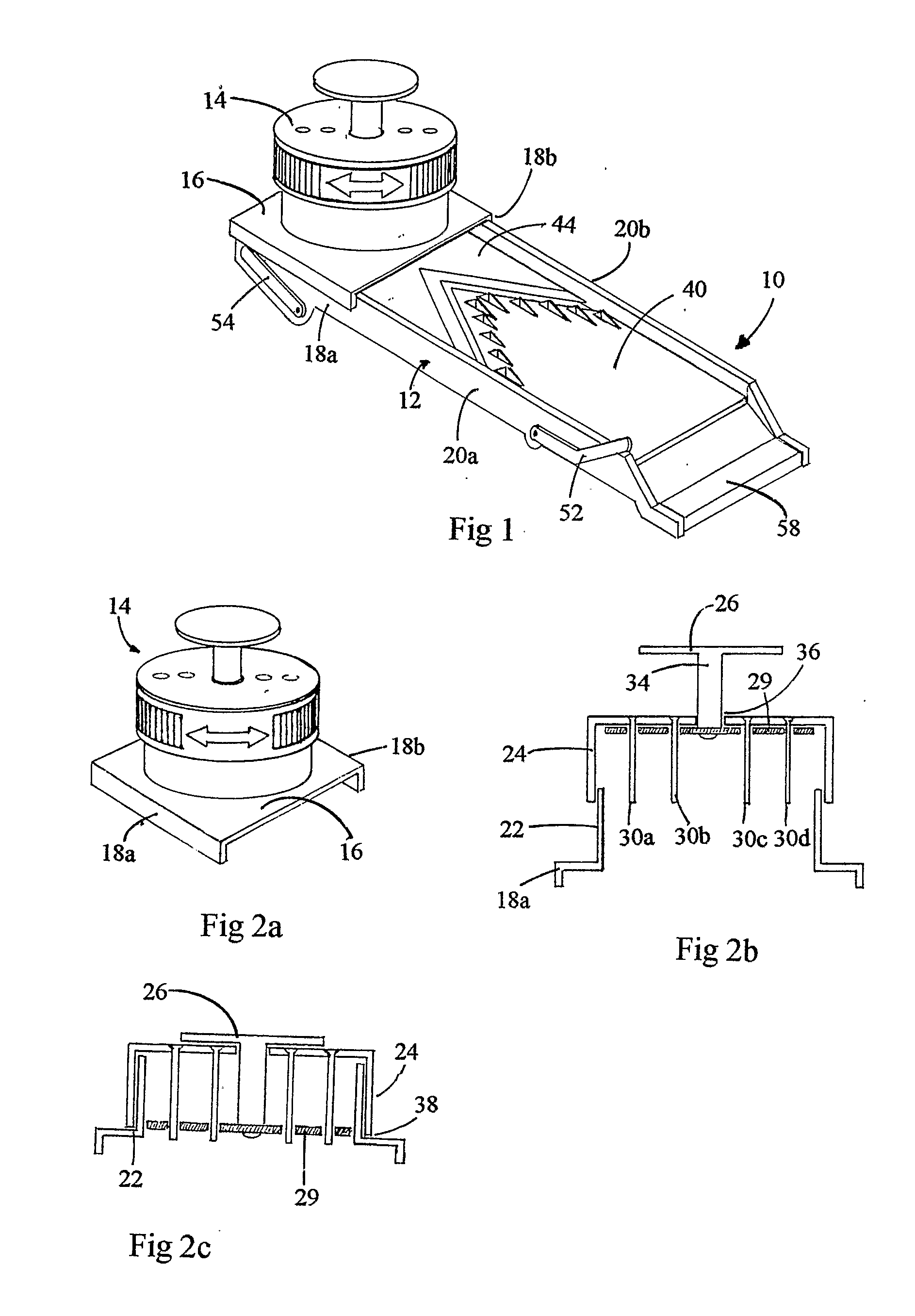
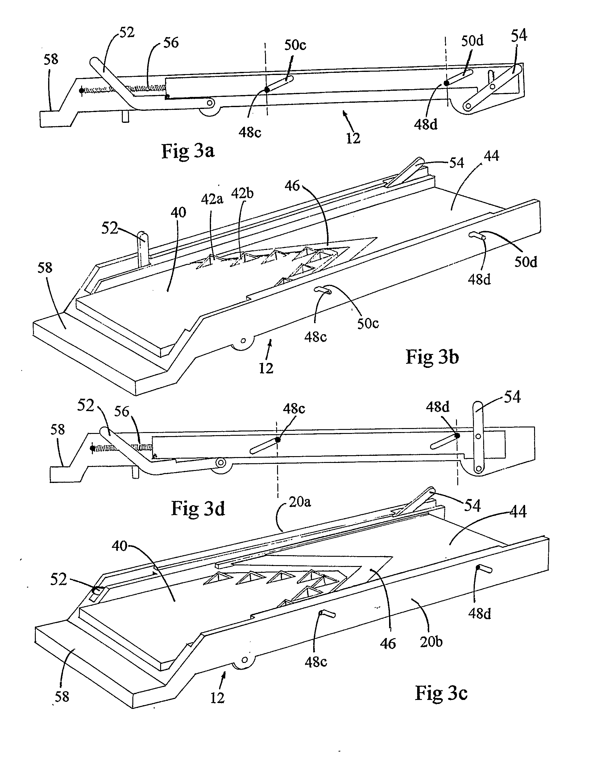
A dicing tool having: a foodstuff holder for holding a block of foodstuff and a cutting base; the cutting base having: a rectangular framework for sliding the foodstuff holder therealong; a first part having an triangular shaped front edge, equally spaced triangular cutting blades being arranged in a triangular arrangement that follows the profile of the triangularly shaped front edge; a handle; a second part having a second upper surface and a right front edge and a left front edge arranged in a deep V shape, with continuous blades attached to the right and left front edges; wherein the second upper surface is always parallel to the first surface and can be slidingly reciprocated between an upper position and a lower position where the horizontal blade is substantially on a level with the first surface and the base of the triangular cutting blades.

Description

FIELD OF THE INVENTION[0001]The present invention is directed to providing a device for dicing food, and a convenient method for food dicing.BACKGROUND[0002]Frequently, there is a desire to chop fruit, vegetables, cheeses, breads, meats and other foodstuffs into cubes or dice. For small quantities, an appropriate knife may be used. The foodstuff is first sliced in one direction. Then the slices are themselves sliced in a second direction, perpendicular thereto, providing chips. Finally, the chips are cut into cubes. The slices and chips may be further sliced or cut individually. For speed and convenient, the sliced foodstuff is turned through ninety degrees to form a stack of slices that is then sliced through in two mutually perpendicular directions.[0003]Knives make one cut at a time, and manually dicing is time consuming, labor intensive and risks cutting fingers, particularly where occasional cooks attempt to dice foodstuffs. Additionally any technique that relies on making one ...

Claims


Application Information

Patent Timeline
IPC IPC(8): A23P1/00A47J43/04B26D1/02B23K31/02B26D1/00B23P17/00
CPCB26D1/553B26D3/18Y10S83/932B26D7/01Y10T29/49B26D3/28Y10T83/9454Y10T83/9498Y10T83/051Y10T83/9495
Inventor TWEG, EDWARD
Owner TWEG EDWARD
Learn More