Bicycle suspension system

a suspension system and bicycle technology, applied in the direction of frictional roller based transmission, steering device, cycle equipment, etc., can solve the problems of reducing the torsional stiffness of these types of assemblies, affecting the torsional stiffness of the suspension system, and undesirable static friction of the bushing, so as to reduce the torsional load, eliminate the components of the heavy suspension assembly, and increase the stiffness

Inactive Publication Date: 2011-03-03
FRANK ROTH CO INC
View PDF13 Cites 10 Cited by
  • Summary
  • Abstract
  • Description
  • Claims
  • Application Information

AI Technical Summary

Benefits of technology

[0022]In its preferred embodiment, the suspension system is comprised of two tubes one fitting inside the other designed to telescope within the other. These tubes are mounted into the head tube or steering tube of the bicycle and include a damping system. Of note are only two sets of axially extending flat sections on each tube along with sets of bearings that are disposed between these flat sections. In addition two longitudinal non-preloaded members are predisposed in the outer tube to allow free linear motion, but no side-to-side motion of the tube relative to each other. Attached to the inner tube is a double-arched crown member designed to reduce torsional loads and increase stiffness specially designed to transmit forces through a single tube to the fork, thus eliminating heavy suspension assembly components.

Problems solved by technology

These bushings have undesirable static friction called “stiction.” Because of this, the suspension systems using such bushings tend to stick and release.
Even with this “U” shaped yoke the torsional stiffness of these types of assemblies is still limited.
In addition the use of two sets of telescoping fork tubes and a steerer tube add considerable weight to the suspension system.
The fork tubes are filled with oil which adds considerable weight.
In terms of weight savings, this design is still not ideal.
Secondly, the highly stressed inner tube must be formed of a material and in a manner such that it bends rather than breaks.
High strength steel is commonly used for the inner tube for this purpose, but it is heavy and counter to the consumer's preference.
Here-to-for, unfortunately, telescope assemblies whose inner tube connects to the fork crown with greater than 70 mm length of travel have been unable to pass stress testing using the present art as described in the aforementioned patents despite the additional costly process of shot-peening and use of expensive high-strength aluminum alloys.

Method used


Image

  • Bicycle suspension system
  • Bicycle suspension system
  • Bicycle suspension system

Examples


Embodiment Construction

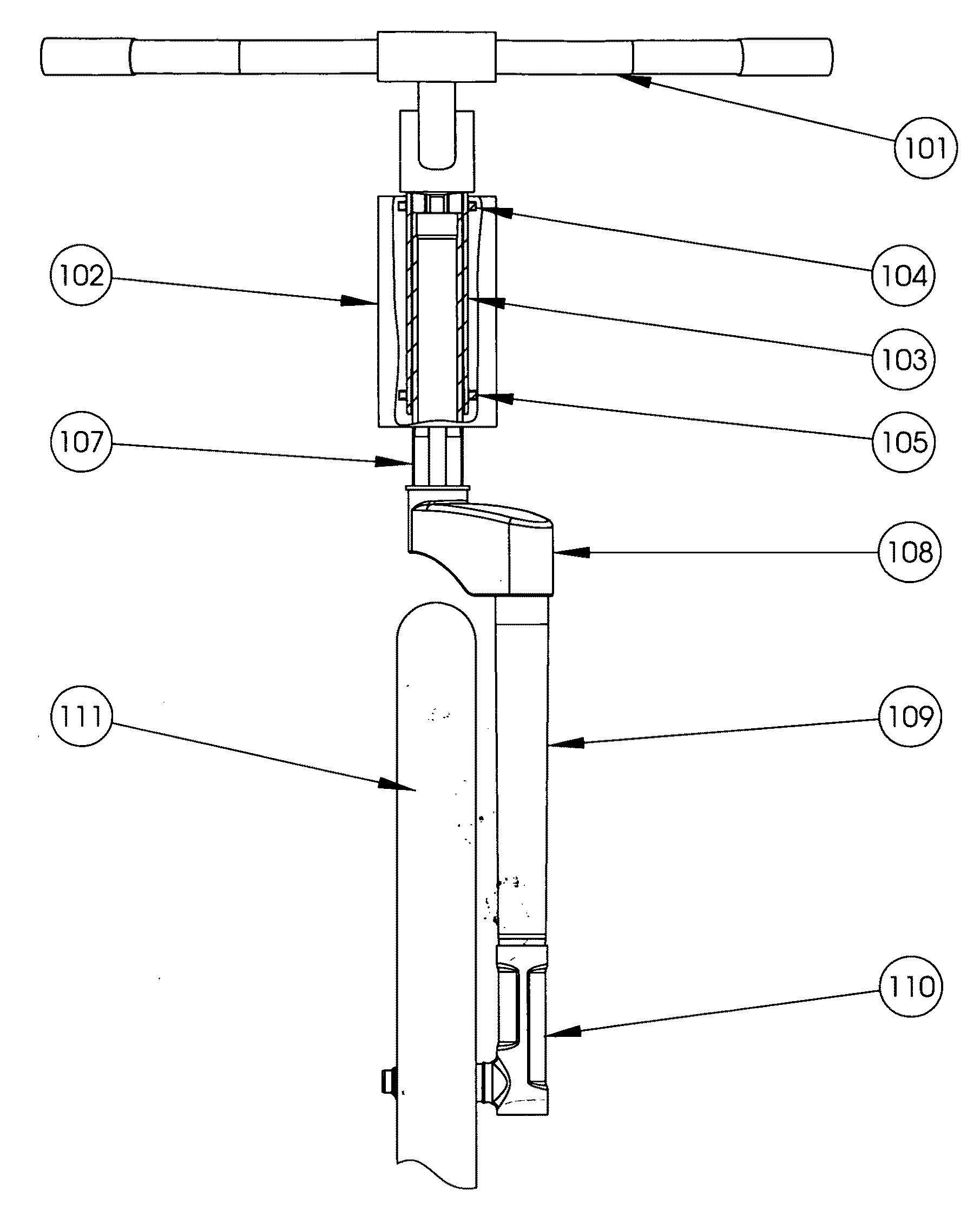
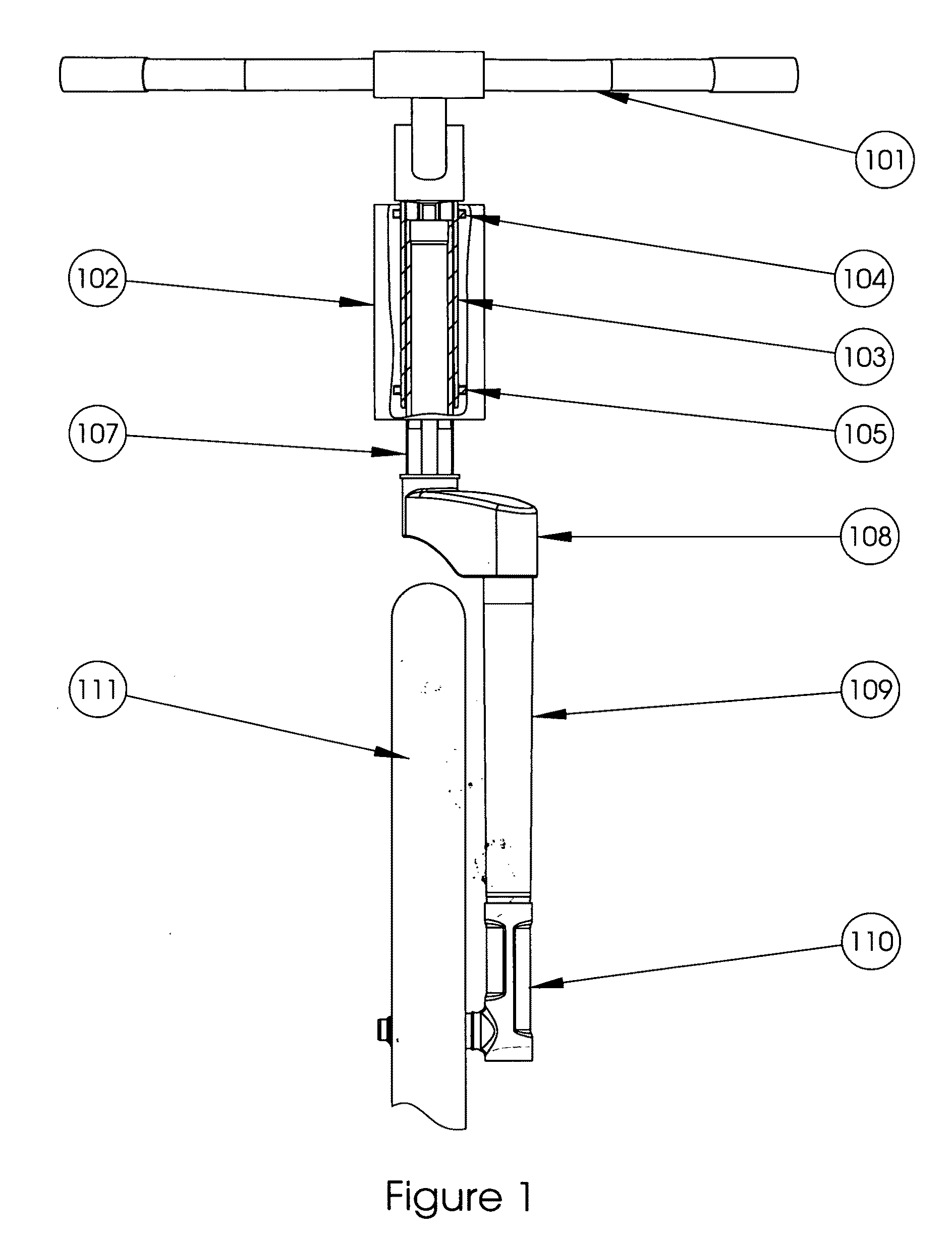
[0035]FIG. 1 shows a front view of a front bicycle suspension system. Handlebars 101 are coupled to an outer tube 103 housed within a head tube 102 (partially shown). The outer tube 103 of the telescoping assembly is pressed into the head tube 102 using upper and lower journal bearings 104-105 to allow for steering rotation. Housed within outer tube 103 is an inner tube 107. Inner tube 107 telescopes within outer tube 103. Coupled to inner tube 107 is a fork crown 108 which is positioned forward to create the trail of the bicycle. Fork tube 109 is a tapered butted tube which is attached to fork crown 108 and a dropout tube 110. Dropout tube 110 contains a small hub stem (not shown) that rides inside the hub (not shown) of wheel 111. As the wheel 111 encounters a bump, the force is translated to inner tube 107. A damper housed in inner tube 107 (not shown in this view), dampens the shock of the bump by allowing inner tube 107 to translate within outer tube 103.

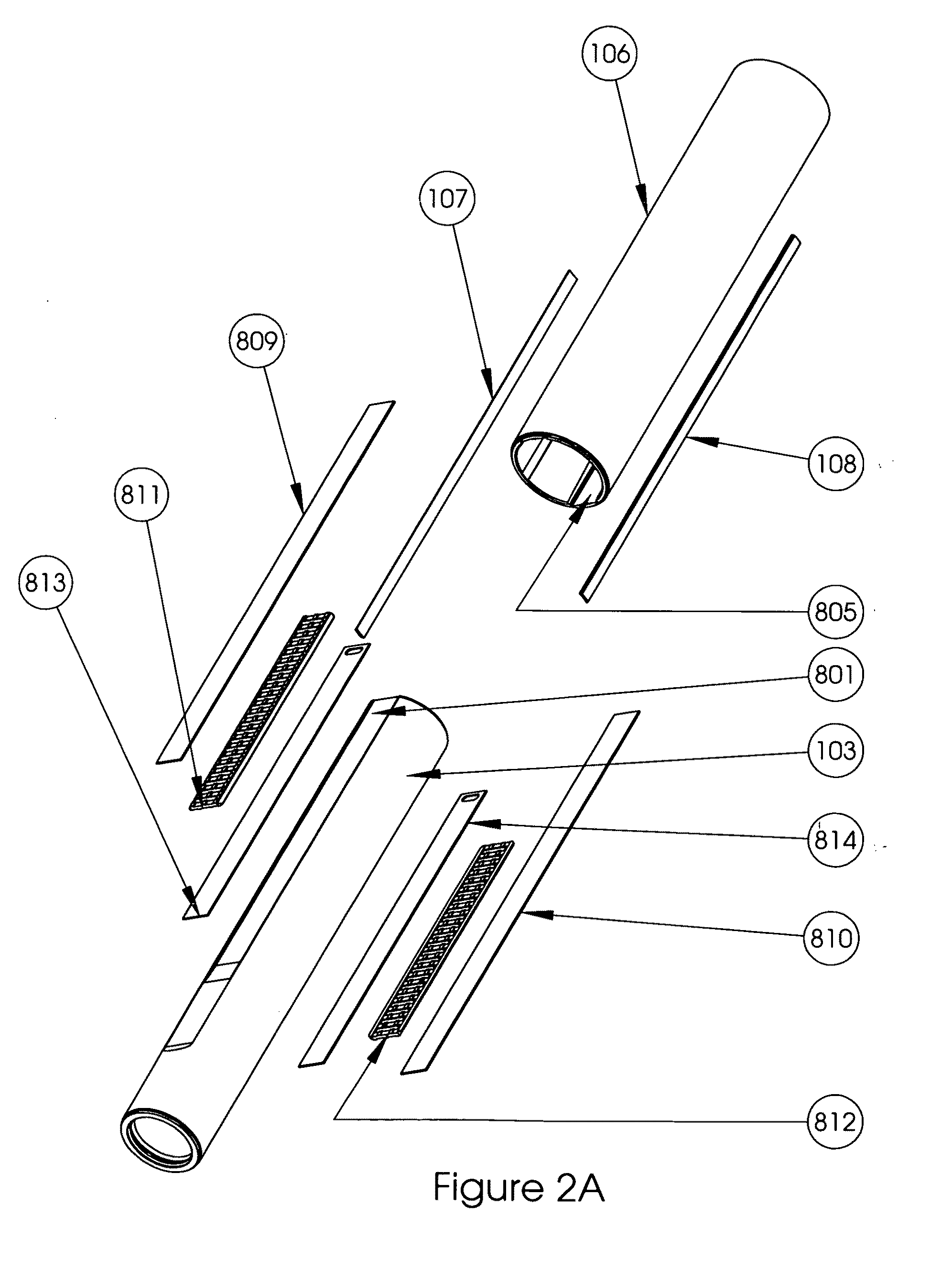
[0036]FIG. 2A is an exp...


PUM


Abstract

In a preferred embodiment, an ultra-light weight suspension fork for bicycles that provides smooth action of the suspension system that hitherto has been unachievable. This fork assembly contains a telescoping mechanism located in the head tube of the bicycle that uses linear roller bearings to reduce stiction and prevent torsional losses, but limits weight by only using two such bearings. Side-to-side load is eliminated by the use of two longitudinal members in close proximity to the inner tube of this telescoping mechanism. The telescoping mechanism is coupled to the wheel via an arched single-sided fork crown designed to maintain torsional and braking stiffness. The arched crown contains arches in two dimensions. The fork crown is coupled to the wheel via a shaped fork tube whose wall is thickened while the outside diameter is reduced so that the connection point to the axle mechanism has the same outside diameter as the fork tube thereby enabling significant strengthening of the assembly.

Description

RELATED APPLICATIONS[0001]Provisional Application No. 61 / 188,221 filed on Aug. 26, 2008.[0002]U.S. Pat. No. 5,320,374 June 1994 Farris et al.[0003]U.S. Pat. No. 5,494,302 February 1996 Farris et al.[0004]U.S. Pat. No. 5,702,092 December 1997 Farris et al.[0005]U.S. Pat. No. 5,924,714 July 1999 Farris et al.[0006]U.S. Pat. No. 6,007,056 December 1999 Farris et al.[0007]U.S. Pat. No. 6,155,541 December 2000 Farris et al.[0008]U.S. Pat. No. 5,509,675 April 1996 Barnett[0009]U.S. Pat. No. 5,195,766 March 1993 Dohrmann et al.[0010]U.S. Pat. No. 4,971,344 November 1990 Turner[0011]U.S. Pat. No. 4,609,202 September 1986 Miyakushi et al.BACKGROUND OF THE INVENTION[0012]1. Field of the Invention[0013]The present invention relates to bicycle suspension systems and more particularly to a lightweight suspension fork assembly. This invention is an improvement on bicycle suspension systems that allows for a torsionally stiff suspension system that is very lightweight. The system addresses drawbac...

Claims


Application Information

Patent Timeline
Patent Type & Authority Applications(United States)
IPC IPC(8): B62K19/32
CPCB62K25/08B62K25/005
Inventor KINZLER, FREDERICK W.WOODWORTH, WALKER P.TOFFOLO, LUIGI J.
Owner FRANK ROTH CO INC
Why Eureka
Try Eureka