
Device for converting wave energy into mechanical energy

a wave energy and mechanical energy technology, applied in the direction of electrical equipment, control systems, sea energy generation, etc., to achieve the effect of adapting or optimising the efficiency of the wave energy

Inactive Publication Date: 2011-03-03
WEPTOS
View PDF6 Cites 7 Cited by
  • Summary
  • Abstract
  • Description
  • Claims
  • Application Information

AI Technical Summary

Benefits of technology

In this context, it will further provide a stable positioning of the wave power plant on the water surface area if the hinge device comprises the anchoring site.
Further utilisation of power can be obtained if the wave power plant further comprises one or more ballast tanks and associated pumps that are configured for filling the ballast tanks with and emptying them of water. Hereby it is possible to regulate the lift of the plant in response to the current wave conditions to the effect that the rotors can be kept immersed into the water surface area in a desired depth with a view to adapting or optimising their efficiency.

Problems solved by technology

It is a constant challenge in the development of wave power plants to optimize the amount of energy that can be extracted from the plant, a commercial penetration of such wave power plants presupposing to a certain extent that, in particular financially, they are able to compete with already existing renewable-energy plants, such as wind turbines and the like.

Method used


Image

  • Device for converting wave energy into mechanical energy
  • Device for converting wave energy into mechanical energy
  • Device for converting wave energy into mechanical energy

Examples


Embodiment Construction

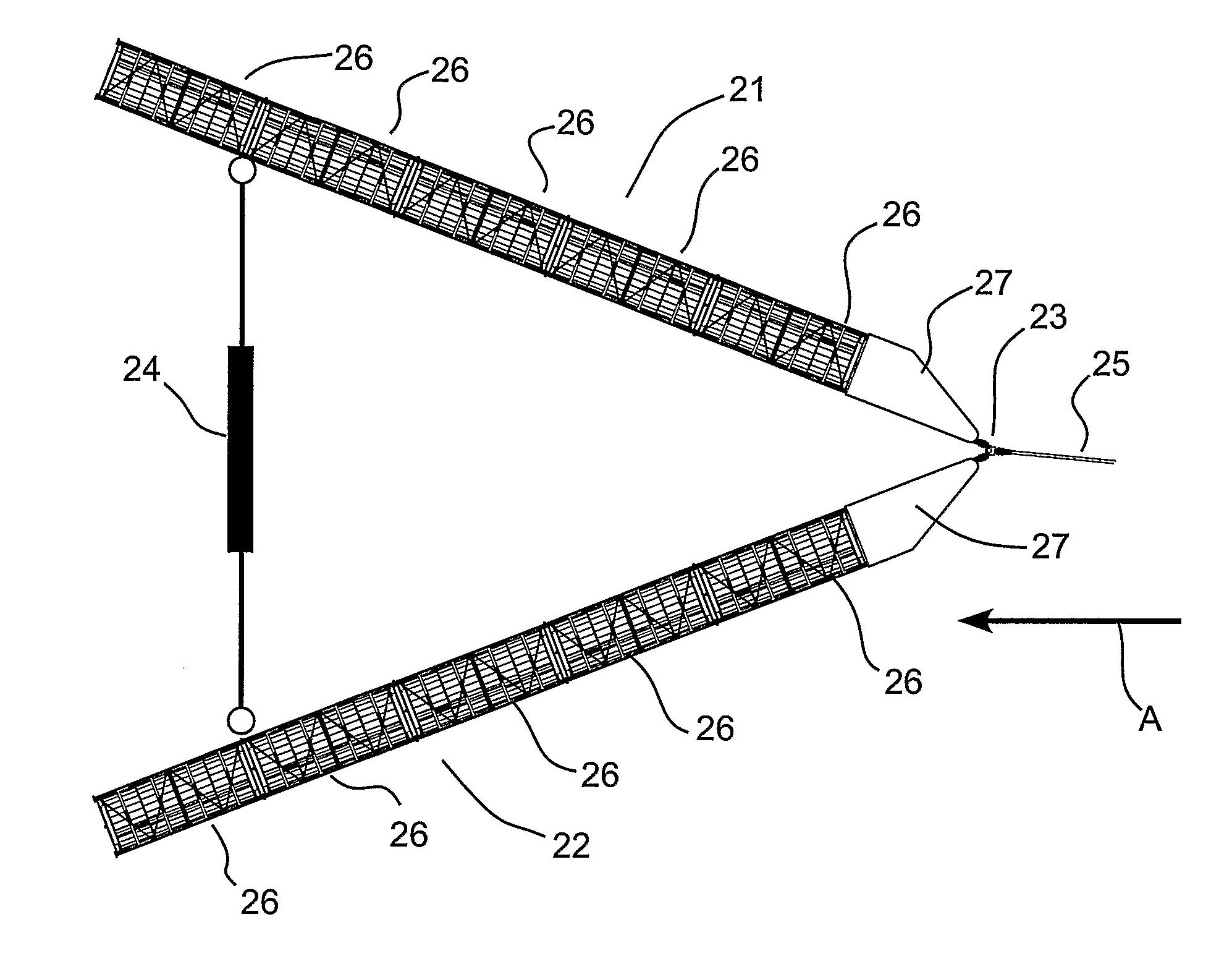
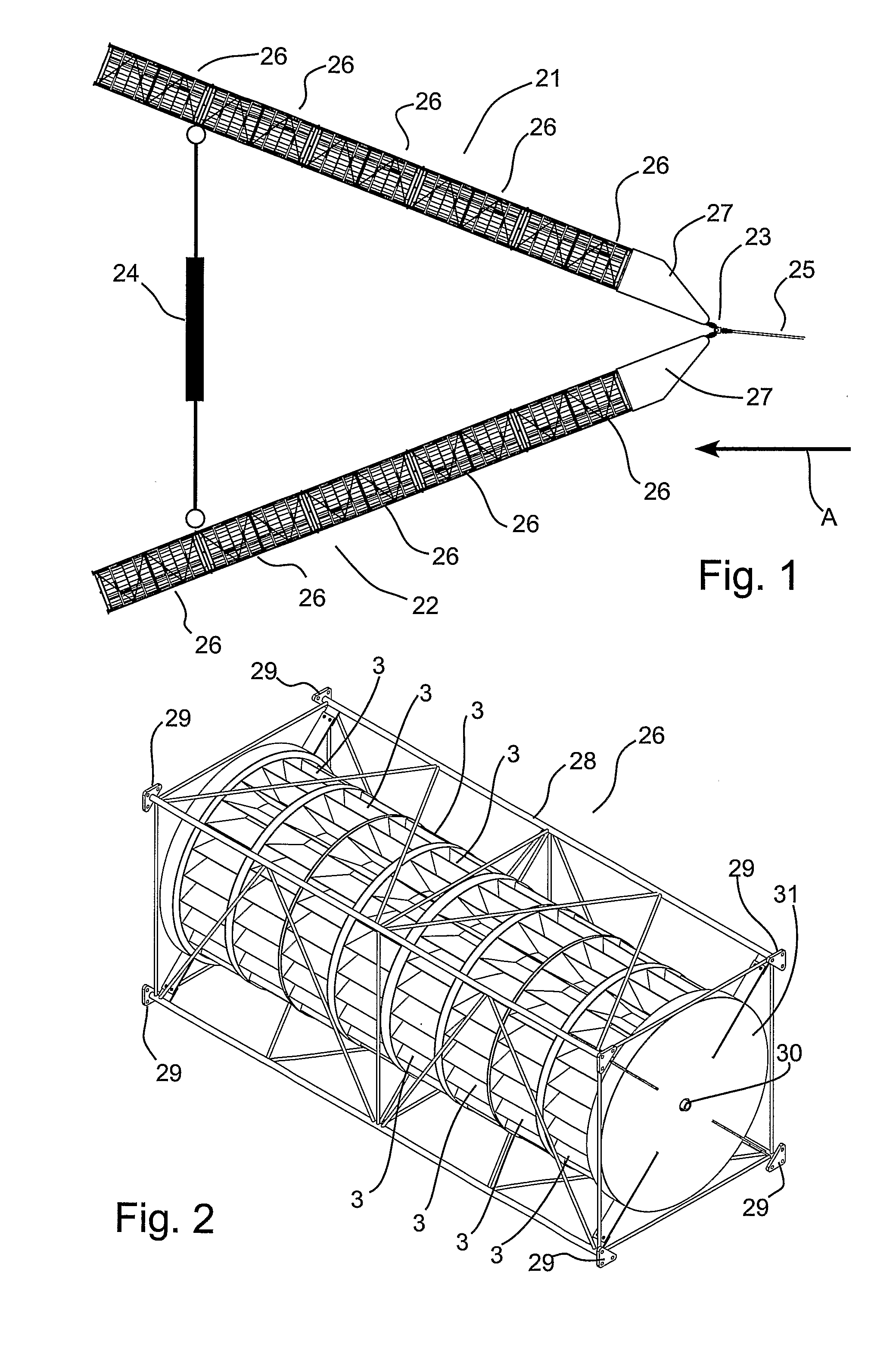
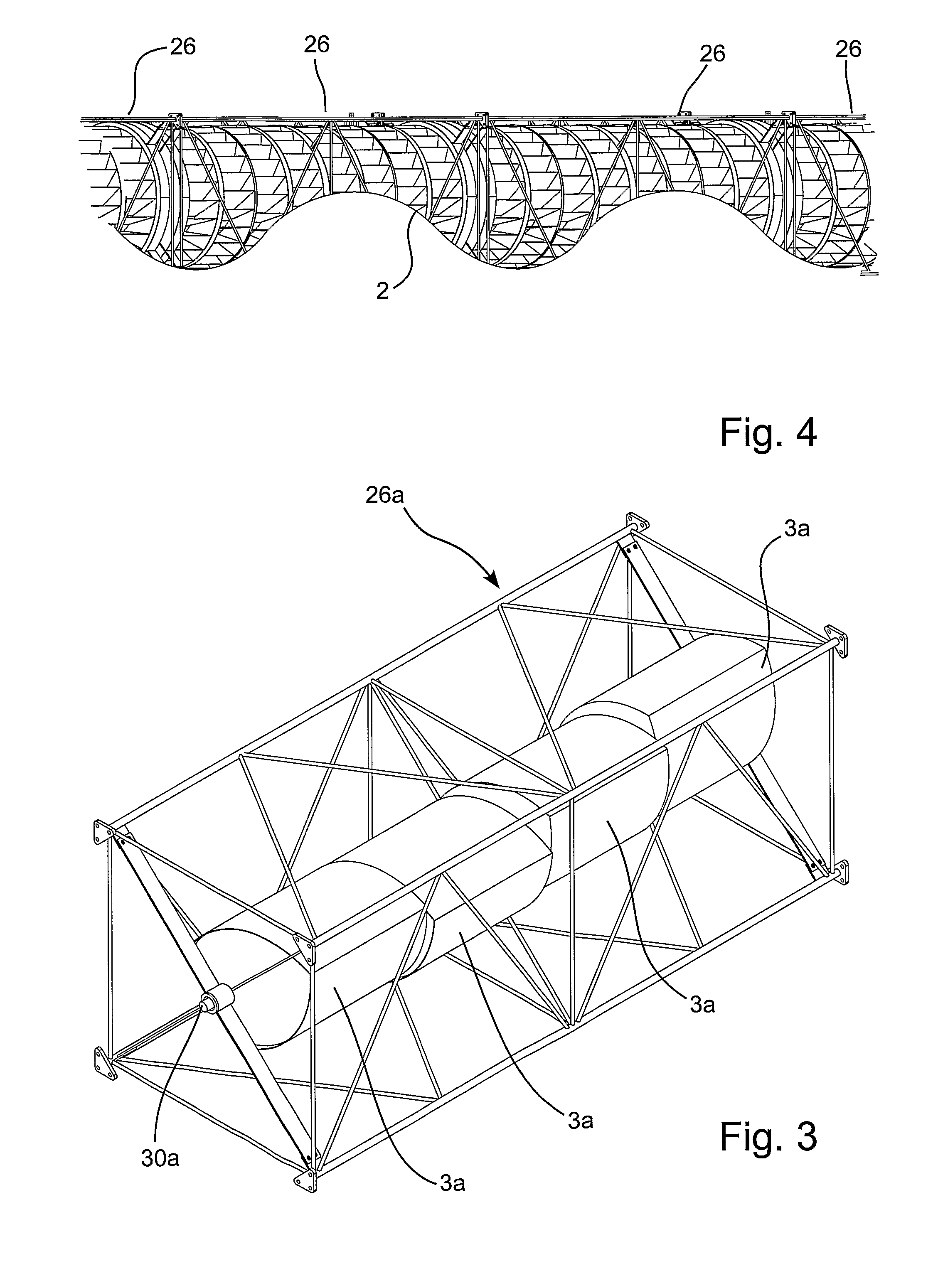
Thus, FIG. 1 shows an embodiment of a wave power plant according to the present invention and wherein the wave power plant is a floating structure, here shown floating on the water surface area 2 where a number of waves have a direction of propagation as indicated by the arrow A to show the mode of operation of such wave power plant. Here the wave power plant has four rotors in the form of water mill wheels 3 that are all partially immersed into the water surface area 2. Those water mill wheels 3 are retained rotatably by means of a not shown shaft relative to the frame construction 1 of the wave power plant, which comprises two beams 4 and 5 that are essentially parallel to the not shown rotor or water mill shafts and that are retained at a fixed angle of 60 degrees relative to each other by means of the transverse booms 6 and 7.

The water mill wheels 3 all being provided with an abundant amount of vanes or dishes 8 that all face with their opening upwards on the side of the water m...


PUM


Abstract

A wave power plant for extracting power from the wave movement of a water surface area, said wave power plant comprising a frame construction in which at least one rotor is journalled, and wherein the rotor is suspended in the frame construction on a rotor shaft which is, in the normal use situation of the wave power plant, essentially horizontal to the effect that the rotor is able to rotate about the rotor shaft which is retained in the frame construction, and wherein means are configured for maintaining each of the rotors partially immersed in a water surface area. The invention provides increased output efficiency of such wave power plant by the rotors being mounted on the rotor shaft via a free-running mechanism which is configured such that the rotor is able to transfer momentum to the rotor shaft essentially only when it rotates the one way about the rotor shaft.

Description

FIELD OF USE OF THE INVENTIONThe present invention relates to a wave power plant for extracting power from the wave movement of a water surface area, said wave power plant comprising a frame construction in which at least two rotors are journalled, and wherein each rotor is suspended in the frame construction on a rotor shaft which is, in the normal use situation of the wave power plant, essentially horizontal to the effect that the rotor is able to rotate about the rotor shaft which is retained in the frame construction, and wherein means are configured for maintaining each of the rotors partially immersed in a water surface area, and where the wave power plant is a floating structure that comprises at least two rotor shafts wherein at least one rotor is arranged on each rotor shaft, and wherein the frame construction comprises an anchoring point configured for mooring the wave power plant, and is configured such that it retains the two non-parallel rotor shafts in such a manner th...

Claims


Application Information

Patent Timeline
IPC IPC(8): F03B13/14
CPCY02E10/38F03B13/184Y02E10/30
Inventor LARSEN, TOMMY
Owner WEPTOS
Learn More