Direct-current motor and manufacturing method for the direct-current motor

a manufacturing method and technology of direct-current motor, applied in the direction of windings, stator/rotor bodies, solid insulation, etc., can solve the problems of generating great vibration on the direct-current motor, reducing the power output and the size of the direct-current motor is undesirably increased, so as to prevent the effect of being enlarged and preventing vibration

Inactive Publication Date: 2011-03-03
DENSO CORP
View PDF9 Cites 43 Cited by
  • Summary
  • Abstract
  • Description
  • Claims
  • Application Information

AI Technical Summary

Benefits of technology

[0006]Accordingly, it is an objective of the present invention to provide a direct-current motor that is prevent

Problems solved by technology

Thus, the size of the direct-current motor is undesirably increased.
When reducing the axial length of the coil end portions to prevent the size of the direct-current motor from increasing, the number of turns of the armature coils need

Method used


Image

  • Direct-current motor and manufacturing method for the direct-current motor
  • Direct-current motor and manufacturing method for the direct-current motor
  • Direct-current motor and manufacturing method for the direct-current motor

Examples


first embodiment

[0053]the present invention will now be described with reference to drawings.

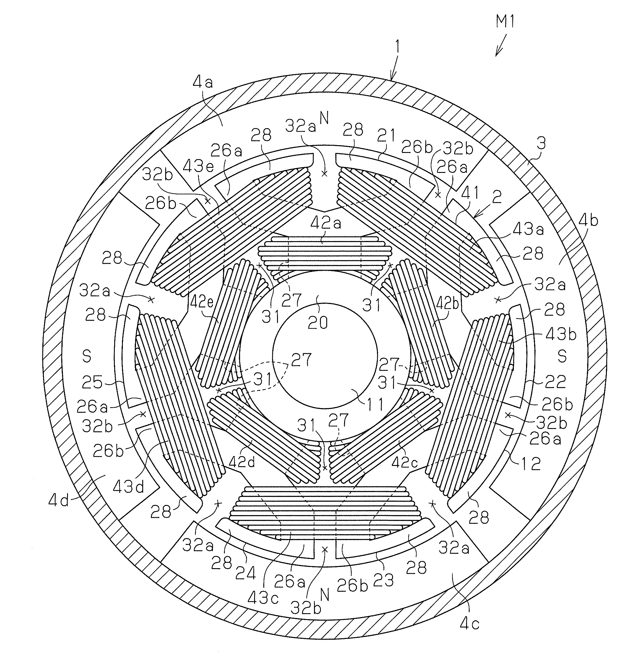
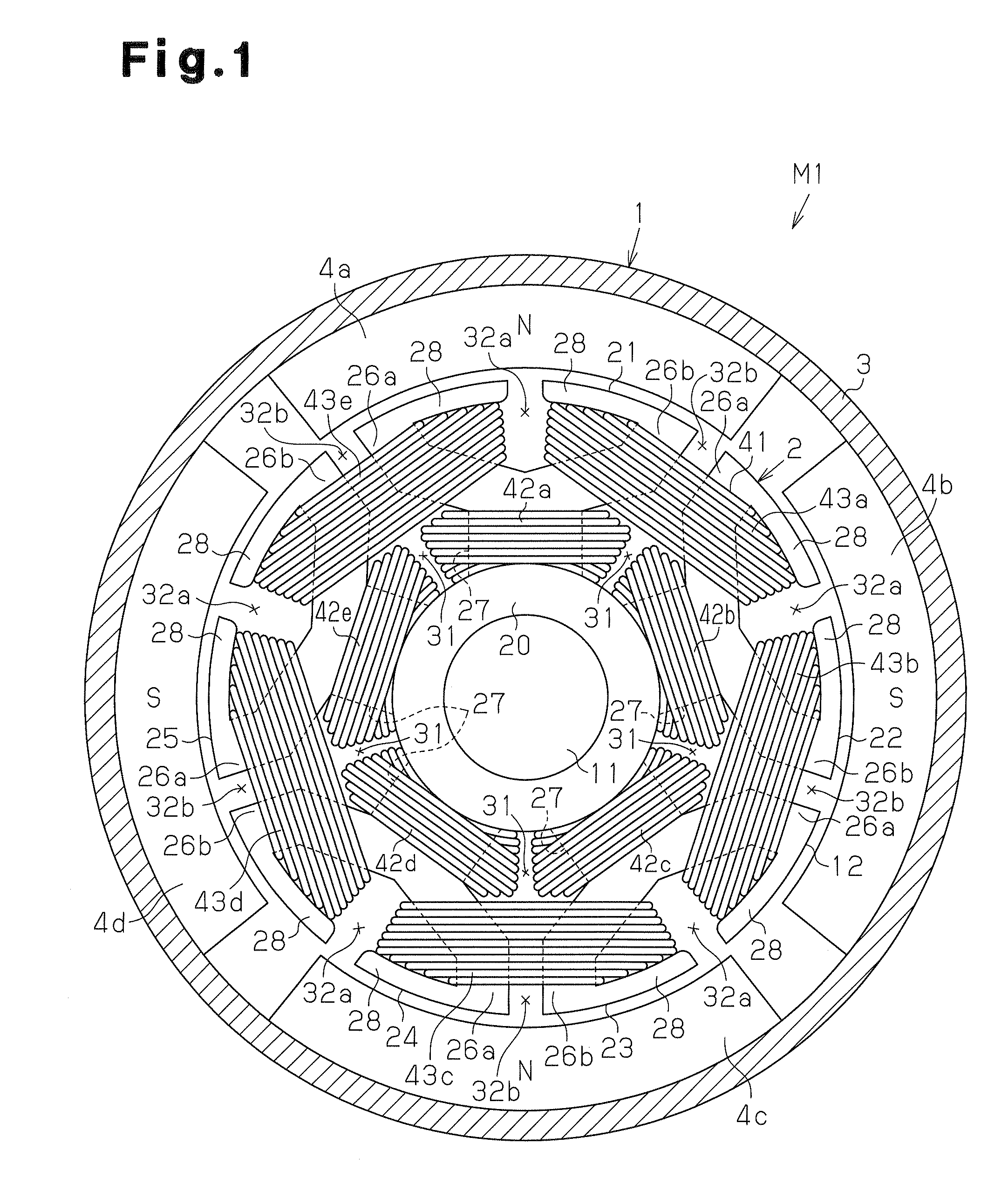
[0054]FIG. 1 shows a cross-sectional view of a direct-current motor M1 according to the first embodiment. The direct-current motor M1 includes a stator 1 and an armature 2 as shown in FIG. 1. The stator 1 includes a substantially cylindrical yoke housing 3. Four magnets 4a to 4d serving as magnetic poles are attached to the inner circumferential surface of the yoke housing 3. The magnets 4a to 4d are arranged at equal angular intervals (in the present embodiment, intervals of 90°) in the circumferential direction. The magnets 4a to 4d are arranged such that the north poles and the south poles are alternately arranged in the circumferential direction. The number of the magnetic poles P of the direct-current motor M1 is four.

[0055]As shown in FIGS. 1 and 2, the armature 2 is arranged radially inward of the stator 1. The armature 2 includes a rotary shaft 11, a substantially columnar armature core 12, which is...

third embodiment

[0120]FIG. 14 shows a diagrammatic developed view of the direct-current motor M4. The direct-current motor M4 differs from the direct-current motor M3 of the third embodiment in the structure of outer layer coils 203a to 203h in the armature 201.

[0121]Eight inner layer coils 202a to 202h and eight outer layer coils 203a to 203h are wound around the armature core 142 as in the third embodiment. The outer layer coils 203a to 203h that are wound around the circumferentially adjacent two branched tooth portions 26a, 26b of the circumferentially adjacent teeth include inner coil portions 211a to 211h that are wound around the proximal end of the branched tooth portions 26a, 26b and outer coil portions 212a to 212h that are wound around the distal end of the branched tooth portions 26a, 26b. In FIG. 14, the inner layer coils 202a to 202h are shown by medium lines, the inner coil portions 211a to 211h are shown by alternate long and short dash lines, and the outer coil portions 212a to 212...

fifth embodiment

[0129]the present invention will now be described with reference to the drawings. In the present embodiment, the same reference numerals are given to those components that are the same as the corresponding components of the first to fourth embodiments and detailed explanations are omitted.


PUM

PropertyMeasurementUnit
Lengthaaaaaaaaaa
Diameteraaaaaaaaaa
Electrical resistanceaaaaaaaaaa

Abstract

A motor is provided that includes magnetic poles, an armature core, armature coils, a commutator, and power supply brushes. The armature core includes teeth arranged in the circumferential direction to extend in a radial pattern. The armature coils include inner layer coils and outer layer coils. Each of the inner layer coils is wound around radially proximal end portions of two circumferentially adjacent teeth or a radially proximal end portion of one of the teeth. The inner layer coils are arranged in the circumferential direction without overlapping each other in the radial direction. Each of the outer layer coils is wound around radially distal end portions of two circumferentially adjacent teeth by distributed winding. The outer layer coils are arranged radially outward of the inner layer coils and are arranged in the circumferential direction without overlapping each other in the radial direction. The circumferential center of the inner layer coils and the circumferential center of the outer layer coils are displaced in the circumferential direction.

Description

BACKGROUND OF THE INVENTION[0001]The present invention relates to a direct-current motor and a method for manufacturing the direct-current motor.[0002]Conventionally, direct-current motors have been proposed that include a stator, which has magnetic poles arranged along the circumferential direction, and an armature, which faces the stator in the radial direction. The armature includes an armature core, which has teeth (salient poles) extending in a radial pattern. Armature coils are wound around the armature core in such a manner that the armature coils pass through slots formed between the circumferentially adjacent teeth.[0003]For example, Japanese Laid-Open Patent Publication No. 2007-116813 discloses a direct-current motor that includes an armature core around which armature coils are wound by distributed winding, in which the armature coils each extend over a number of teeth. Japanese Laid-Open Patent Publication No. 2004-88915 discloses a direct-current motor that includes an...

Claims


Application Information

Patent Timeline
IPC IPC(8): H02K23/36H01R39/38H02K15/08
CPCH02K1/146Y10T29/49012H02K23/405H02K23/36
Inventor DOUSHITA, YOSHIAKIKAWAI, KEITAMORIYA, KAZUMITSUYAMAMOTO, TOSHIOHORIKAWA, MASAYASHIMIZU, MASAAKI
Owner DENSO CORP
Why Eureka
Try Eureka