Illumination System Comprising A Light Source And A Control Unit And An Illumination Control System For Controlling A Light Source By Multiple User Interface Surfaces

a control system and light source technology, applied in the direction of light sources, lighting devices, instruments, etc., can solve the problems of inadvertently addressing the further functionality, counterintuitive pulling force on the control element for the user of the conventional control unit, etc., to improve the user control capability, simplify the configuration of the control system, and increase flexibility

Active Publication Date: 2011-03-03
ELDOLAB HLDG
View PDF2 Cites 15 Cited by
  • Summary
  • Abstract
  • Description
  • Claims
  • Application Information

AI Technical Summary

Benefits of technology

[0023]In an illumination control system according to the present invention, each of the first and second control unit is arranged to, depending on the input of the user of the system, act either as a master (corresponding to the first operating mode), thereby controlling the light source and informing the other control unit to operate as a slave (corresponding to the second operating mode). In the illumination control system according to the present invention, an input by the user determines which control unit obtains the master-role, whereupon the assigned master control unit provides a request to the other control unit (or units), requesting the other control unit to set or resets its status to the second operating mode. By enabling the master-role to be handed over to a further control unit rather than providing a central control unit with the master-role, the configuration of the control system is simplified. Compared to a conventional master-slave system with one master control unit that is continuously in control, there is no requirement to configure the central master control unit or to reconfigure it each time a control unit is added to the control system.
[0024]In the illumination control system according to the present invention, each control unit which acts as sla

Problems solved by technology

As such, exerting a pulling force on the control element would be counterintuitive for a user of the conventional control unit.
Therefore

Method used


Image

  • Illumination System Comprising A Light Source And A Control Unit And An Illumination Control System For Controlling A Light Source By Multiple User Interface Surfaces
  • Illumination System Comprising A Light Source And A Control Unit And An Illumination Control System For Controlling A Light Source By Multiple User Interface Surfaces
  • Illumination System Comprising A Light Source And A Control Unit And An Illumination Control System For Controlling A Light Source By Multiple User Interface Surfaces

Examples


Embodiment Construction

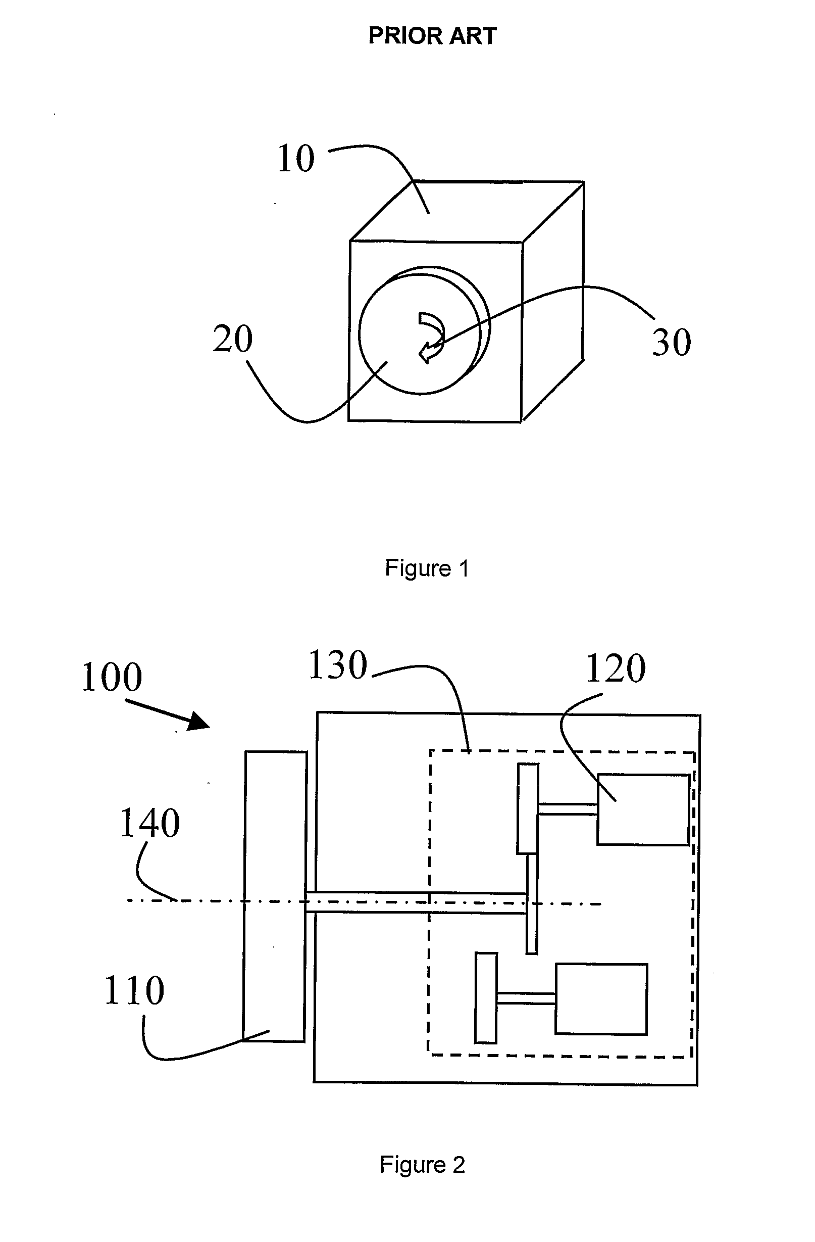
[0046]FIG. 1 schematically shows a conventional control unit 10 for a light source, the control unit comprising a control element 20. In the embodiment as shown, the control element 20 comprises a knob which can be rotated in a direction as indicated by the arrow 30. By rotating the knob, the intensity of the light source (not shown) can be modified.

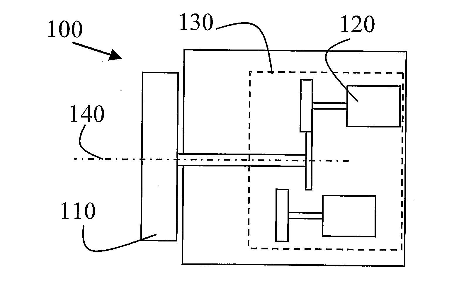
[0047]FIG. 2 schematically shows an XY cross-sectional view of a first control unit of an illumination system according to the invention. The control unit 100 comprises a control element 110 which, in the position as shown, engages with a transducer 120 of a transducer unit 130. By operating the control element 110 (e.g. rotating the element about an axis 140), a characteristic of the transducer 120 can be modified. This changed characteristic can be applied by the control unit to generate a control signal for e.g. controlling the intensity of the light source (not shown) that is controlled by the control unit. It will be appreciated by ...


PUM


Abstract

An Illumination system comprising a light source (1010) and a control unit (CU1) for controlling the light source is described. The control unit is arranged to operate in a first state to control a first illumination parameter of the light source and in a second state to control a second illumination parameter, a transition from the first state to the second state is obtained by providing a pulling force to a control element of the control unit.

Description

CROSS-REFERENCE TO RELATED APPLICATIONS[0001]This application is the National Stage of International Application No. PCT / NL2009 / 000031, filed Feb. 13, 2009, which claims the benefit of International Application No. PCT / NL2008 / 000044, filed Feb. 15, 2008, the contents of which is incorporated by reference herein.FIELD OF THE INVENTION[0002]Illumination systems comprising a control unit for controlling a light source such as switches or dimmers are known. They are widely applied to control an illumination parameter of the light source such as the intensity of the light source. The light source can e.g. be a light bulb or a halogen lamp.BACKGROUND OF THE INVENTION[0003]In a known arrangement, such a control unit comprises a control element such as a knob or a selector for changing the intensity of the light source. In general, a displacement of the control element can be converted by the control unit into a control signal for controlling the illumination parameter. Such a conversion ca...

Claims


Application Information

Patent Timeline
IPC IPC(8): H05B41/24H05B37/02
CPCH05B37/0254H05B37/0209H05B47/18H05B47/185H05B47/165
Inventor VAN DOORNE, HUBERT JOHAN MARIE ROBERTWELTEN, PETRUS JOHANNES MARIA
Owner ELDOLAB HLDG
Why Eureka
Try Eureka