Proximity sensors

a technology of proximity sensors and sensors, applied in the field of proximity sensors, can solve problems such as false positive alerts, and achieve the effect of minimising reflections from the body and minimising the proportion of the radiated power of the transmit signal

Active Publication Date: 2011-03-03
G4S MONITORING TECH
View PDF26 Cites 40 Cited by
  • Summary
  • Abstract
  • Description
  • Claims
  • Application Information

AI Technical Summary

Benefits of technology

[0006]In the case where the proximity sensor is intended to be incorporated into a device such as a monitoring tag or a portable tracking device, for example, that might be carried or worn close to the body of an individual then it will be readily appreciated that the body can produce unwanted reflections of the transmit signal back to the antenna even when no blocking object is present. If such reflections are detected then they can lead to false positive alerts. The proximity sensor is therefore preferably designed to provide an alert only if an object that might be used to block the transmission and / or receipt of the main electromagnetic signal is detected to be in the proximity of the device. The positioning of the antenna within the device can be an important factor in minimising reflections from the body. For example, the antenna may be positioned so that it is spaced away from the body when the device is in use. Spacing the antenna about a quarter wavelength (or a significant part thereof) of the transmit signal away from the body may have the effect of minimising the proportion of the radiated power of the transmit signal that is reflected back to the antenna by the body of the individual. The detector threshold or any other structural or operational feature of the proximity sensor or its associated device can be selected to enable the proximity sensor to distinguish properly between reflections from the body and those from a blocking object.
[0008]The oscillator can be configured to supply a continuous or pulsed transmit signal to the antenna. To minimise temperature drift issues that are often present in conventional RF detectors, and enhance detection sensitivity, then the detector can be configured to receive a pulsed receive signal. The oscillator can be on / off modulated such that the receive signal that is coupled to the detector is a pulsed signal.

Problems solved by technology

If such reflections are detected then they can lead to false positive alerts.

Method used


Image

  • Proximity sensors
  • Proximity sensors

Examples


Embodiment Construction

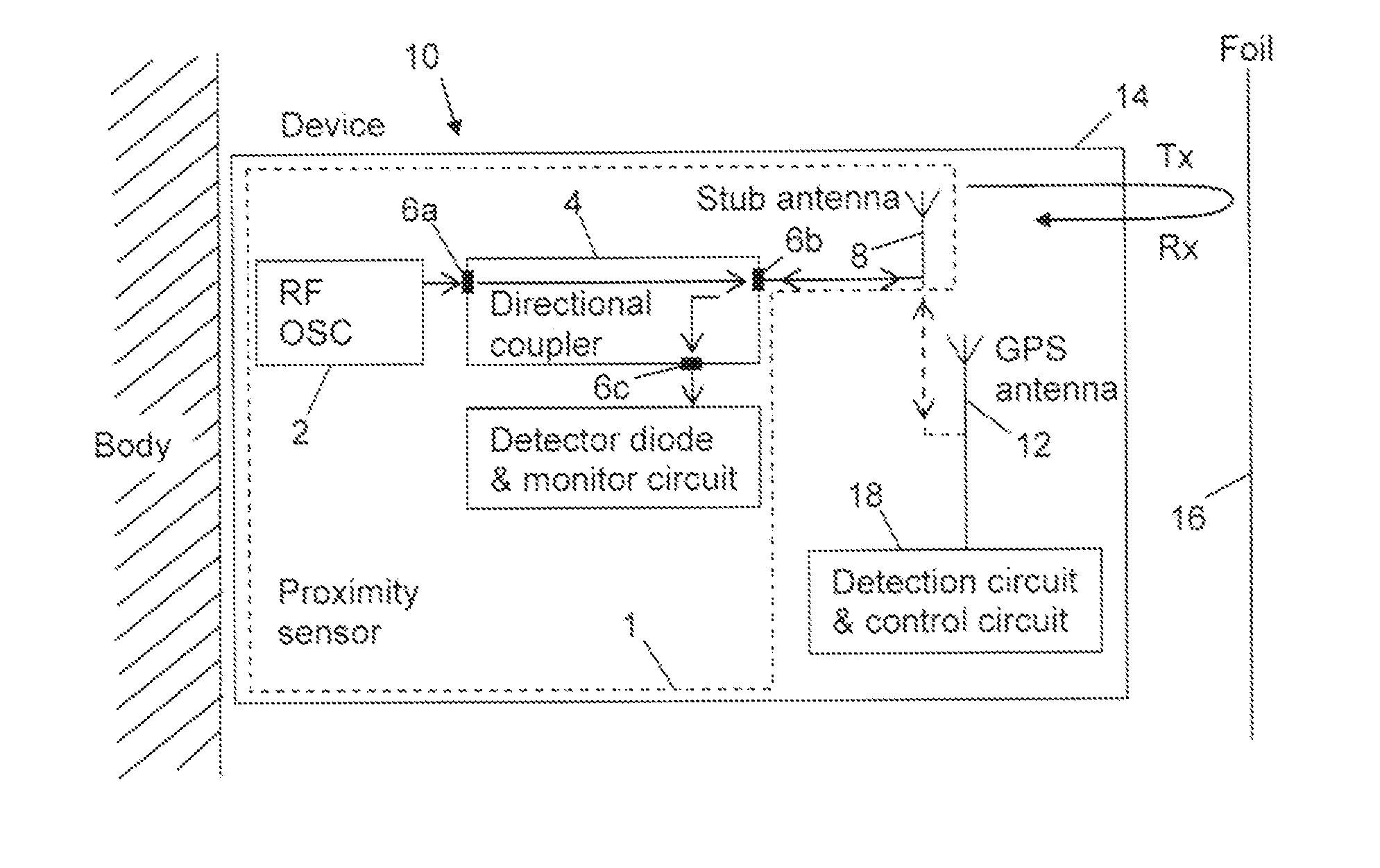
[0019]A foil sensor 1 according to the present invention will be described with reference to FIGS. 1 and 2. To aid integration, the foil sensor 1 is preferably small, low cost and uses surface mount technology. A preferred operating frequency for the foil sensor is 2.45 GHz because this is a popular ISM band and suitable RF components are readily available from commercial suppliers.

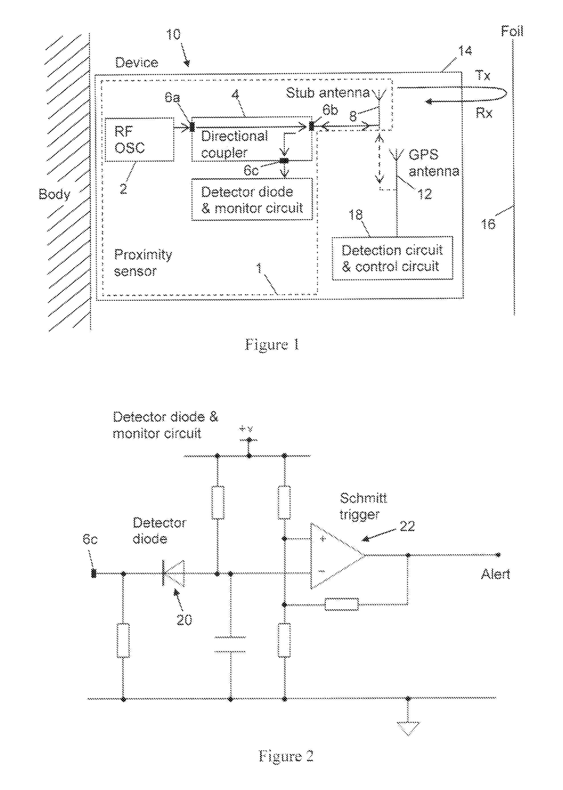
[0020]The foil sensor 1 includes a low power RF oscillator 2. An RF directional coupler 4 has a first port 6a and a second port 6b. A third port 6c operates either as an isolated port or a coupled port depending on the direction of RF power flow through the directional coupler 4. This will be explained in more detail below.

[0021]The first port 6a is connected to the oscillator 2 by a 50 Ω transmission line.

[0022]The second port 6b is connected to a stub antenna 8 such as a printed quarter wave stub antenna.

[0023]The foil sensor 1 is incorporated into a device 10 such as a monitoring tag (e.g. an offender ...


PUM


Abstract

A proximity sensor can be used with a device such as a monitoring tag or portable tracking device that relies on GPS signals or other radio-frequency signals. The proximity sensor determines if the signals are being deliberately blocked by an object such as metal foil being placed in proximity to the device. The sensor includes an oscillator, a directional coupler and an antenna. A third port of the directional coupler acts as a coupled port when RF power that has been transmitted by the antenna is reflected back to the antenna by a blocking object. The reflected RF power passes along a main line of the directional coupler and a proportion is coupled to the third port. A detector provides an alert if the magnitude of the power of the transmit signal that is reflected back to the antenna in the form of a receive signal exceeds a threshold.

Description

FIELD OF THE INVENTION[0001]The present invention relates to proximity sensors, and in particular to proximity sensors that can be used to detect the close proximity of an object that might be used to block an electromagnetic signal.BACKGROUND ART[0002]The proximity sensor can be designed to be incorporated into a monitoring tag that might be secured around the appendage of an individual, for example. The monitoring tags can include a location detection means for detecting if the individual has moved outside a designated area within which electromagnetic (e.g. radio-frequency or RF) signals can be exchanged between the monitoring tag and a base unit. The monitoring tags can also include a global positioning system (GPS) device that uses electromagnetic signals (e.g. GPS signals) to determine the location of the individual and to track and record their movement. The proximity sensor can also be designed to be incorporated into a portable tracking device that is carried or worn by the...

Claims


Application Information

Patent Timeline
Patent Type & Authority Applications(United States)
IPC IPC(8): G08B21/00
CPCG01S5/0018G01S19/21G01S13/04
Inventor ANDERSON, JOHNHUGHES, ALED
Owner G4S MONITORING TECH
Why Eureka
Try Eureka