Pixel clocking method and apparatus

a clock source circuit and clock source circuit technology, applied in the field of pixel clocking methods and apparatuses, can solve the problems of limited the total number of simultaneous displays, the relative high cost of implementing several of these clock source circuits, and the inability to achieve the exact timing of multiple displays

Active Publication Date: 2011-03-03
ATI TECH INC
View PDF33 Cites 4 Cited by
  • Summary
  • Abstract
  • Description
  • Claims
  • Application Information

AI Technical Summary

Benefits of technology

The method and apparatus provide, among other advantages, a reduced number of clock circuits required to drive multiple displays having various timing characteristics. Reducing the number of required clock circuits in the apparatus advantageously reduces the size and cost of the apparatus. In addition, power consumption is also reduced due to the reduced number of clock circuits. Other advantages will be recognized by those of ordinary skill in the art.

Problems solved by technology

The relatively high cost of implementing several of these clock source circuits has been one factor that has limited the total number of simultaneous displays that could be driven at a time by a single GPU.
However, in many applications, the multiple displays may not have the same exact timing.
In this example, the two monitors could not be driven using a shared clock synthesis circuit because they both don't have the exact same timing scheme.

Method used


Image

  • Pixel clocking method and apparatus
  • Pixel clocking method and apparatus
  • Pixel clocking method and apparatus

Examples


Embodiment Construction

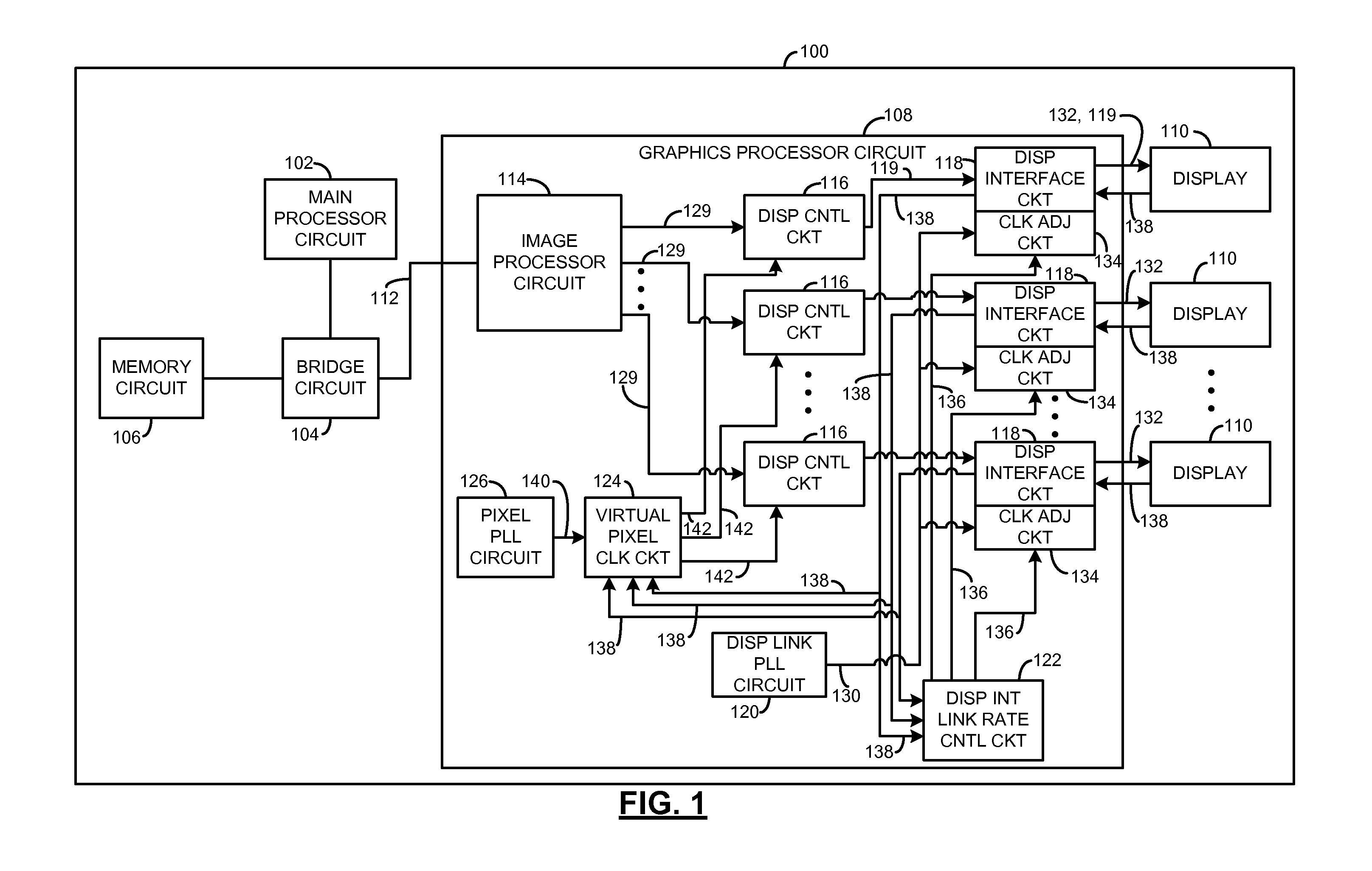
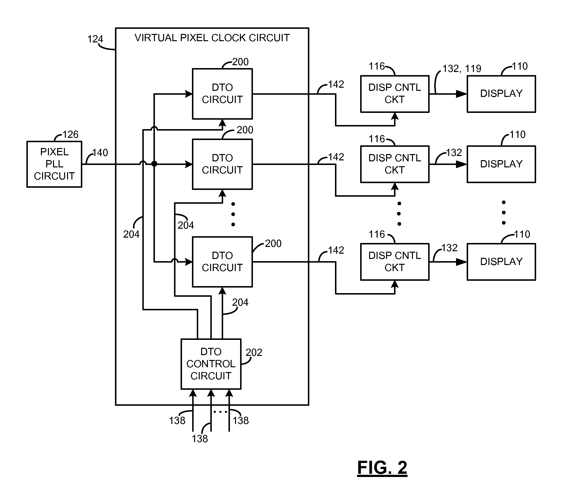
In one example, an apparatus includes a display link clock circuit and a plurality of display interface circuits. The clock circuit provides a common display link clock signal. The display interface circuits each provide a respective display link clock signal in response to the common display link clock signal. One of the display link clock signals is at a different clock speed than another of the display link clock signals. In another example, the apparatus includes a pixel clock circuit and a virtual pixel clock circuit. The pixel clock circuit provides a common pixel clock signal. The virtual pixel clock circuit provides a plurality of pixel clock signals in response to the common pixel clock signal. One of the virtual pixel clock signals is at a different clock speed than another of the virtual pixel clock signals. A related method is also disclosed.

The method and apparatus provide, among other advantages, a reduced number of clock circuits required to drive multiple displays ha...


PUM


Abstract

An apparatus includes a clock circuit and a virtual pixel clock circuit. The clock circuit provides a common clock signal. The virtual pixel clock circuit provides a plurality of pixel clock signals in response to the common clock signal. One of the virtual pixel clock signals is at a different clock speed than another of the plurality of virtual pixel clock signals.

Description

FIELDThe present disclosure generally relates to pixel clocking methods and apparatus, and more particularly, to methods and apparatus for providing multiple pixel clocking signals for multiple displays.BACKGROUNDTraditional display interfaces such as VGA, DVI, HDMI, LVDS require a dedicated clock generation circuit for each simultaneously active output connected to a source device such as a PC or GPU. The relatively high cost of implementing several of these clock source circuits has been one factor that has limited the total number of simultaneous displays that could be driven at a time by a single GPU.It is known to drive multiple displays at a time with a shared clock synthesis circuit using a reference clock such as a crystal, only if all these displays use the exact same timing (e.g., resolution, refresh rate and pixel clock rate). However, in many applications, the multiple displays may not have the same exact timing. For example, a consumer may have one type of display that ...

Claims


Application Information

Patent Timeline
Patent Type & Authority Applications(United States)
IPC IPC(8): G06T1/00G09G5/00
CPCG06F3/1431G09G2370/047G09G2300/023G09G5/12
Inventor GLEN, DAVID I.J.CARTER, COLLIS QUINNSHTUTMAN, NATANABARCA, GABRIELWANG, JONATHAN
Owner ATI TECH INC
Why Eureka
Try Eureka