
Recording apparatus

a recording apparatus and recording technology, applied in the field of recording apparatuses, can solve problems such as unfavorable drying and drying, and achieve the effects of avoiding unfavorable drying

Active Publication Date: 2011-03-03
SEIKO EPSON CORP
View PDF3 Cites 7 Cited by
  • Summary
  • Abstract
  • Description
  • Claims
  • Application Information

AI Technical Summary

Benefits of technology

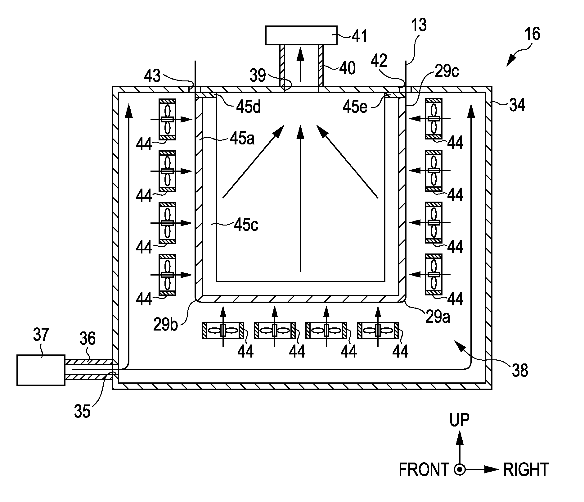
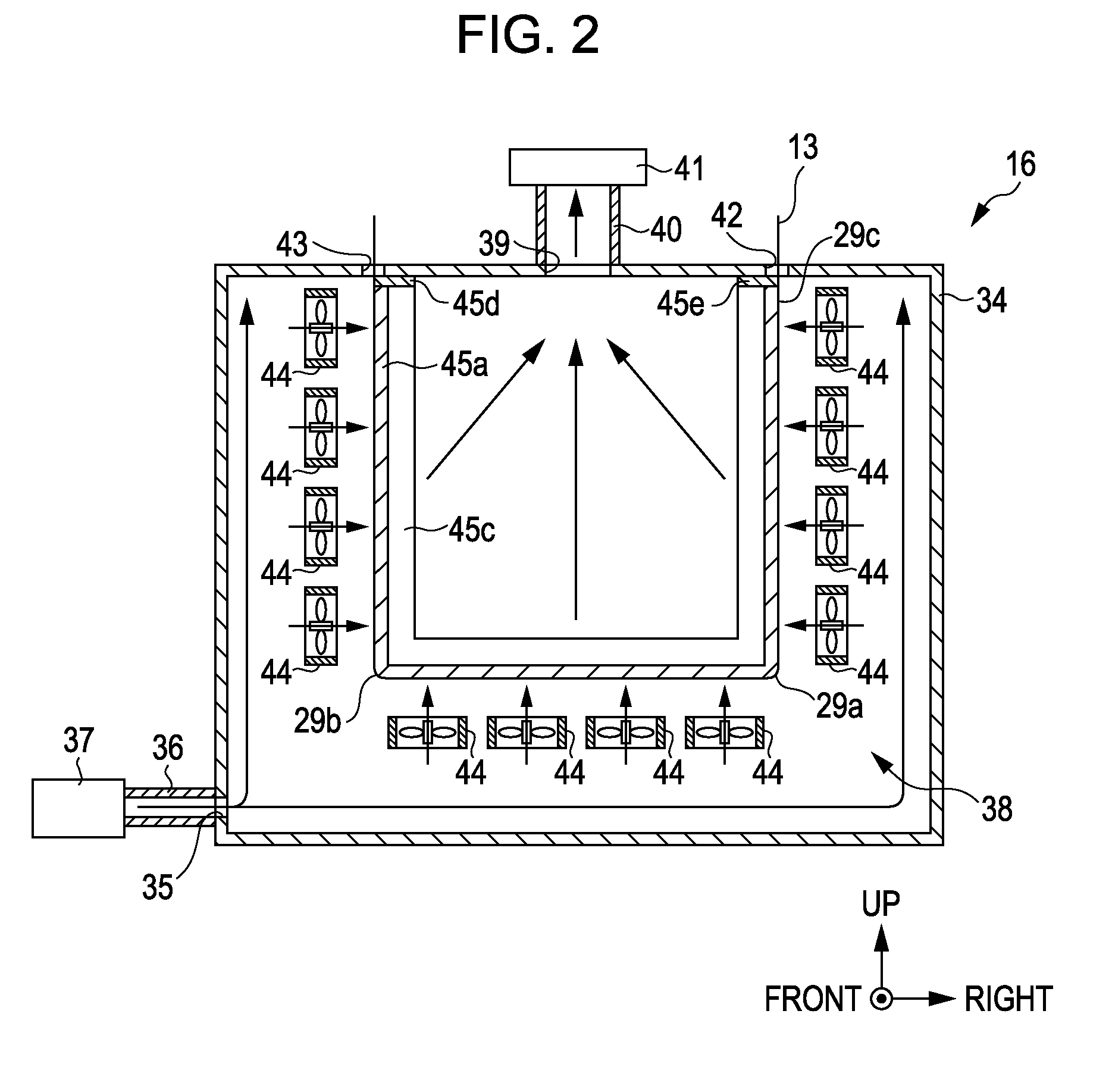
[0011]With such a configuration, the contact member forms the bent section in the midstream position of the transport path of the recording medium in the drying unit, and increases a transport distance of the recording medium in the drying unit. Thus, the recording medium is configured so that the recording material adhered to the recording medium by means of the recording unit can be sufficiently heated and fixed in the process of passing through the drying unit. In this respect, even though the contact member is heated in the drying unit, the heated contact member comes in continuous contact with the entire region of the recording medium in the state of being stopped in transporting in the drying unit through the contact surface thereof. Thus, the contact member uniformly heats the surface of the recording medium opposite to the surface thereof to which the recording material is adhered, through the contact surface thereof in the process in which the recording medium passes through the drying unit, and thus, the recording material adhered to the recording medium can be uniformly dried.
[0015]With such a configuration, since the contact member comes in contact with the recording medium to be continuous along the transport direction of the recording medium without intermittence, it is possible to uniformly heat and dry the recording material adhered to the recording medium.
[0017]With such a configuration, since the contact member is made of a metallic material having a high level of heat conductivity, it is possible to shorten time required when the contact member is preheated up to the same temperature as in the inside of the drying unit, when the recording apparatus starts its operation.
[0019]With such a configuration, the blowing unit can reliably dry the recording material adhered to the recording medium by blowing the warm air towards the recording material adhered to the recording medium in the drying unit.
[0021]With such a configuration, since the contact member is configured so that the sliding resistance of the contact surface being in contact with the recording medium becomes small, it is possible to restrict the recording medium from being abraded in the process of sliding on the contact surface of the contact member.

Problems solved by technology

Accordingly, the continuous recording medium is overheated by the take-up roller in the process of passing through the forcible drying section at a part thereof which comes in contact with the take-up roller in the state of being stopped in transporting, and thus, the unevenness may occur in the drying.

Method used


Image

  • Recording apparatus
  • Recording apparatus
  • Recording apparatus

Examples


Embodiment Construction

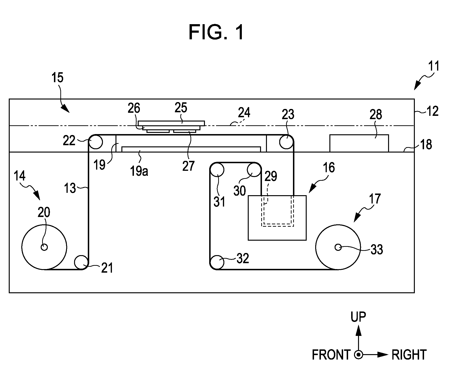
[0030]Hereinafter, an ink jet printer (hereinafter, referred to as a “printer”) according to a specific embodiment of the present invention will be described with reference to FIGS. 1 to 3. In this description, the terms of a “front and rear direction”, a “left and right direction” and an “up and down direction” are used to represent directions indicated by arrows in FIG. 1.

[0031]As shown in FIG. 1, the printer 11 which is a recording apparatus includes a main body case 12 having a rectangular parallelepiped shape. In the main body case 12 are installed a reeling out section 14 which reels out a continuous recording medium 13 as a recording medium having an elongated shape, a printing chamber 15 in which ink as a recording material is ejected onto the continuous recording medium 13 to perform printing, a drying device 16 as a drying unit which performs a drying process with respect to the continuous recording medium 13 to which the ink is adhered by the printing, and a rolling secti...


PUM


Abstract

A recording apparatus includes a transport unit that intermittently transports an elongated recording medium from an upstream side to a downstream side as the lengthwise direction of the recording medium moves along a transport path. A recording unit adheres a recording material to the recording medium when the recording medium is stopped in a midstream position of the transport path. A drying unit downstream from the recording unit heats and dries the recording material. A contact member has a contact surface continuous contact with the surface of the recording medium opposite the surface thereof to which the recording material is adhered, from the time when the recording medium enters into the drying unit to the time when the recording medium is discharged from the drying unit. The contact member forms the transport path with the contact surface having at least one bent section in the drying unit.

Description

[0001]The entire disclosure of Japanese Patent Application No. 2009-196443 filed Aug. 27, 2009 is expressly incorporated by reference in its entirety herein.BACKGROUND[0002]1. Technical Field[0003]The present invention relates to a recording apparatus such as an ink jet printer.[0004]2. Related Art[0005]In the related art, there is well known an ink jet printer (hereinafter, referred to as a “printer”) as a kind of a recording apparatus in which a recording material is adhered to a target to perform recording. Recently, there has been proposed a technology in which a liquid (recording material) is ejected to a continuous recording medium (target) using such a printer to continuously print a plurality of unit images which will be used as labels by being cut later. (For example, refer to JP-A-2009-73012.)[0006]That is, in the printer as disclosed in JP-A-2009-73012, a platen is installed in a midstream position of a transport path of a continuous recording medium, and ink (recording m...

Claims


Application Information

Patent Timeline
IPC IPC(8): B41J2/01
CPCB41J15/16B41J11/002B41J11/00242B41J11/0022
Inventor TOYA, AKIHIROKAWAKAMI, SHINJI
Owner SEIKO EPSON CORP
Learn More