
Polarization conversion apparatus and projection system using same

a technology which is applied in the field of polarization conversion apparatus and projection system using same, can solve the problems of complex structure and high cost non-uniform light with s-polarization emitted from the two polarization conversion systems, and complex design of polarization conversion system array, etc., to achieve the effect of reducing the difficulty of designing an appropriate light source, reducing the cost and improving the optical performan

Inactive Publication Date: 2011-03-03
BUTTERFLY TECH SHENZHEN
View PDF9 Cites 11 Cited by
  • Summary
  • Abstract
  • Description
  • Claims
  • Application Information

AI Technical Summary

Benefits of technology

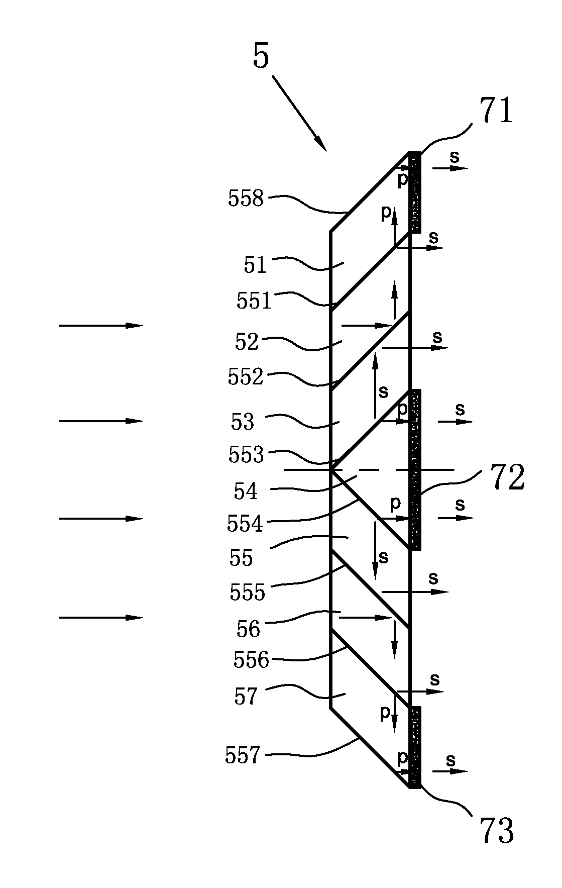
[0007]The present disclosure has been made in the light of the above problems, and an object of the present disclosure is therefore to provide a polarization conversion apparatus. The polarization conversion apparatus is capable of completely converting natural incident light into uniform light with single polarization. The present disclosure also provides a projection system employing the polarization conversion apparatus without the need of micro-lens array. Therefore, the difficulty of designing an appropriate light source can be decreased, and a cost is correspondingly lowered. The projection system can provide an improved optical performance.
[0015]Compared with prior arts, the present disclosure has following advantages.
[0018]There is no need of employing any micro-lens array in the light conversion apparatus for the light from the light source. The light from the light source can directly enter into the polarization conversion apparatus, and is converted to light with single polarization and passes through the polarization beam splitter until it reaches the display chip. Thus, the projection system has a simplified optical design and a decreased cost.

Problems solved by technology

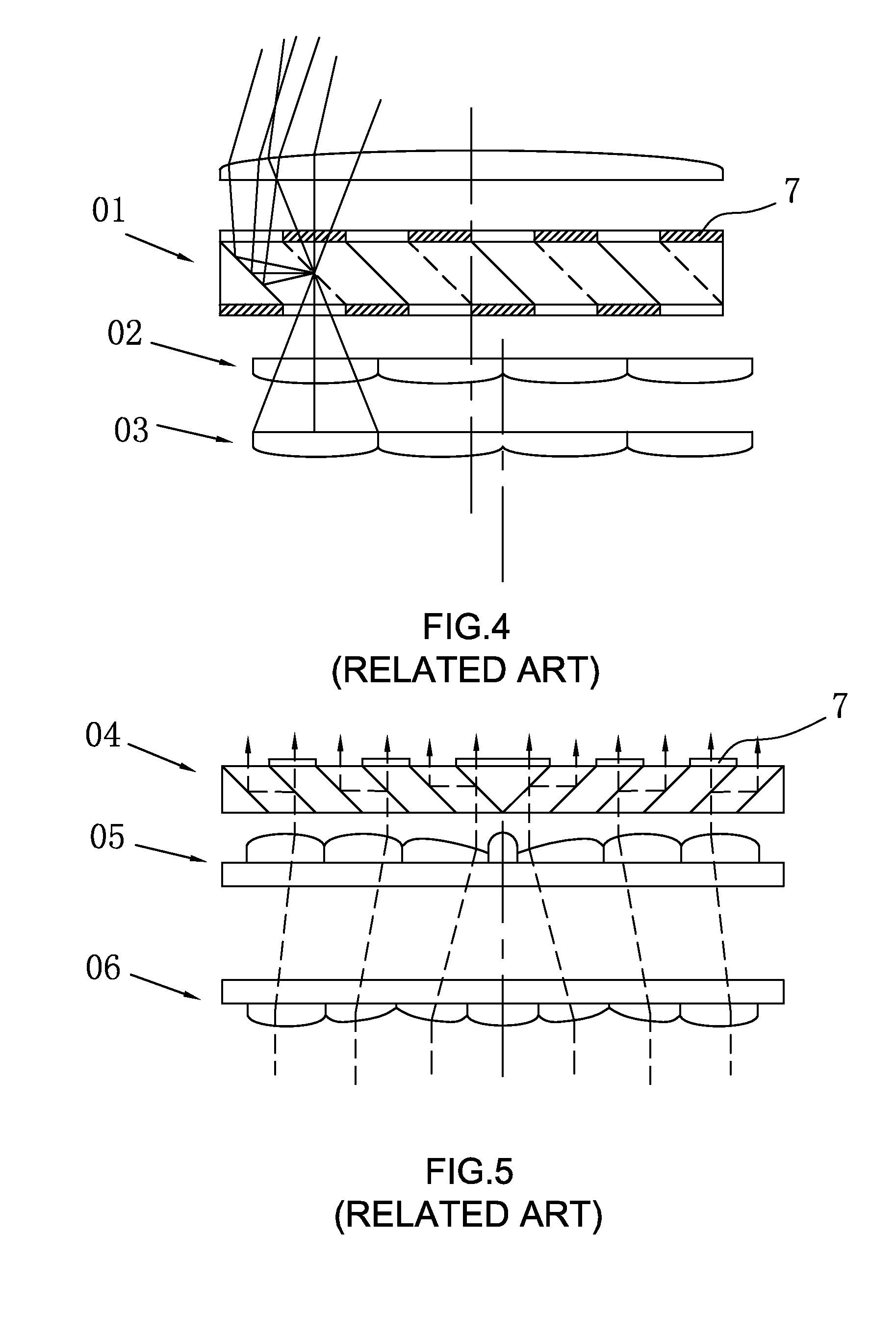
However, light with s-polarization emitting from the two polarization conversion systems is non-uniform.
That is, the polarization conversion system array 01 has a complex structure and a high cost.
However, the polarization conversion system array 04 also obviously has a complex design and a corresponding high cost.

Method used


Image

  • Polarization conversion apparatus and projection system using same
  • Polarization conversion apparatus and projection system using same
  • Polarization conversion apparatus and projection system using same

Examples


Embodiment Construction

[0031]Reference will now be made to the drawings to describe preferred and exemplary embodiments in detail.

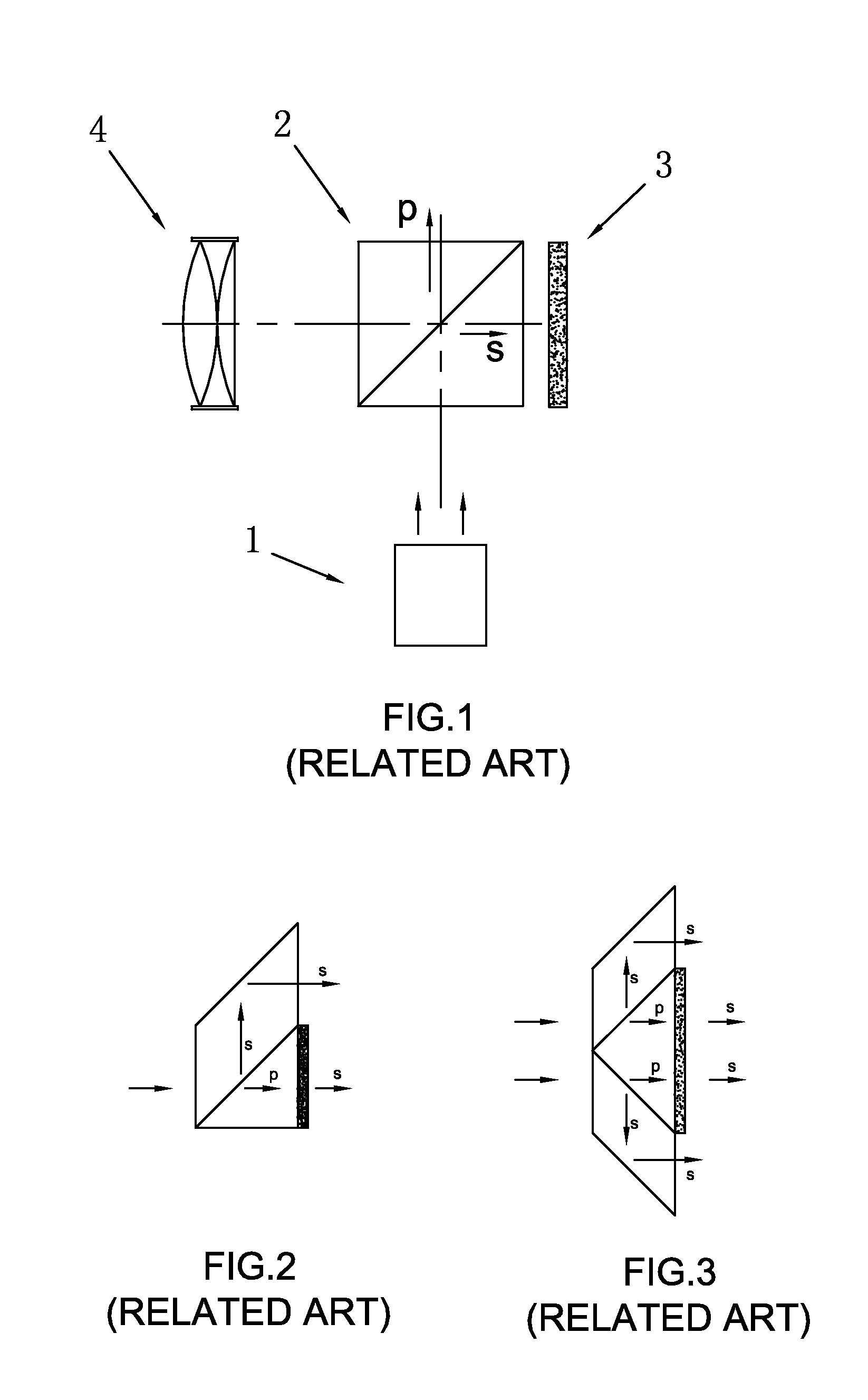
[0032]A first polarization conversion apparatus of the present disclosure is capable of converting natural light into light with s-polarization, and a second polarization conversion apparatus of the present disclosures is capable of converting natural light into light with p-polarization. The first and second polarization conversion apparatuses share the same spirit only with the difference of changing a half-wave plate. For example, the polarization conversion system in FIG. 2 can completely convert the natural light into light with p-polarization if the half-wave plate is moved to the emission surface of the former prism, which simple change has been disclosed by existed patents.

[0033]The first polarization conversion apparatus of the present disclosure is described below.

[0034]Referring to FIG. 6, the polarization conversion apparatus includes seven prisms 51, 52, 53, 54, 55...


PUM


Abstract

A polarization conversion apparatus capable of converting natural incident light into linear light with single polarization for emission includes a plurality of prisms arrayed as a whole component, a plurality of half-wave plates arranged at emission surfaces of some of the prisms, and a plurality of faying surfaces defined inside and a plurality of side surfaces defined outside. Some of the faying surfaces include polarization beam splitting films formed thereon to form polarization beam splitting surfaces, and one faying surface and the side surfaces include total reflection films formed thereon to form total reflection surfaces.

Description

FIELD OF THE DISCLOSURE[0001]The present disclosure relates to a polarization conversion apparatus capable of converting natural light from a light source into linearly polarized light with same polarization, and a single-chipped liquid crystal on silicon (LCOS) projection system using the polarization conversion apparatus.GENERAL BACKGROUND[0002]A typical single-chipped reflective liquid crystal projection system is described in FIG. 1. The projection system includes a light source 1, a polarization beam splitter 2, a reflective liquid crystal panel 3, and a projection lens 4. The light source 1 can be selected from many kinds of light sources, and can include one or more filters for filtering ultraviolet and infrared light, focusing lens assemblies, or a light rod. Light from the light source 1 is split into light with p-polarization and light with s-polarization. The light with s-polarization is used to illuminate the liquid crystal panel 3, while the light with p-polarization em...

Claims


Application Information

Patent Timeline
IPC IPC(8): G02B27/28G03B21/14
CPCG03B21/14G02B27/285G03B21/2073
Inventor QU, LUJIE
Owner BUTTERFLY TECH SHENZHEN
Learn More