Perpendicular magnetic recording system and write head with transverse auxiliary pole for fast switching of write pole magnetization

a technology of magnetic recording system and write head, which is applied in the direction of special recording techniques, maintaining head carrier alignment, instruments, etc., can solve the problems of requiring additional power from the write driver circuitry, limiting the switching time of the main pole of the write head to switch from one magnetization direction to the other, and requiring overshoot. , to achieve the effect of facilitating the magnetization reversal of the write pole and reducing the power consumption

Inactive Publication Date: 2011-03-03
WESTERN DIGITAL TECH INC
View PDF29 Cites 25 Cited by
  • Summary
  • Abstract
  • Description
  • Claims
  • Application Information

AI Technical Summary

Benefits of technology

[0008]The invention relates to a perpendicular magnetic recording system with a write head having a main coil (the write coil) and main pole (the write pole) that directs write flux in a direction perpendicular to the recording layer in the magnetic recording medium, and a transverse auxiliary pole (TAP) that injects auxiliary magnetic flux into the write pole at an angle to the primary or perpendicular axis of the write pole. The additional flux from the TAP, which is injected non-parallel to the primary magnetization of the write pole, exerts a relatively large torque on the magnetization of the write pole, thereby facilitating magnetization reversal of the write pole. The TAP has its longitudinal axis oriented at an angle (greater than 15 degrees) and preferably substantially orthogonal (70 to 90 degrees) to the primary or perpendicular axis of the write pole.

Problems solved by technology

However, the switching time for the main pole of the write head to switch from one magnetization direction to the other is a limiting factor as the data rate is increased.
Also, lower data-rate systems still require additional overshoot of the write current from the disk drive's write driver circuitry to aid in the magnetization reversal.
This additional overshoot requires additional power from the write driver circuitry.

Method used


Image

  • Perpendicular magnetic recording system and write head with transverse auxiliary pole for fast switching of write pole magnetization
  • Perpendicular magnetic recording system and write head with transverse auxiliary pole for fast switching of write pole magnetization
  • Perpendicular magnetic recording system and write head with transverse auxiliary pole for fast switching of write pole magnetization

Examples


Embodiment Construction

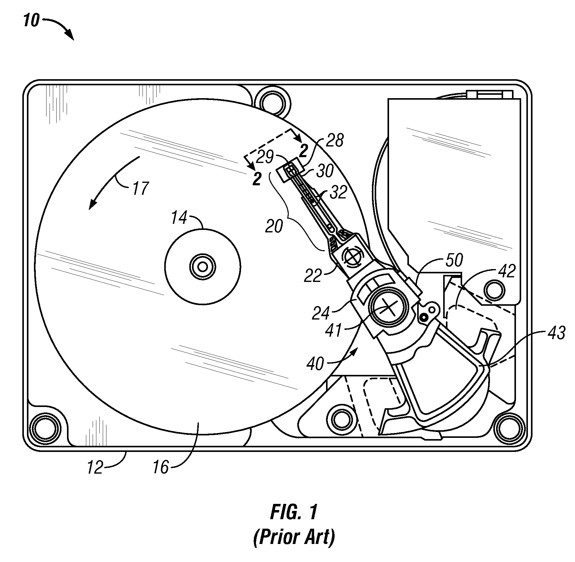
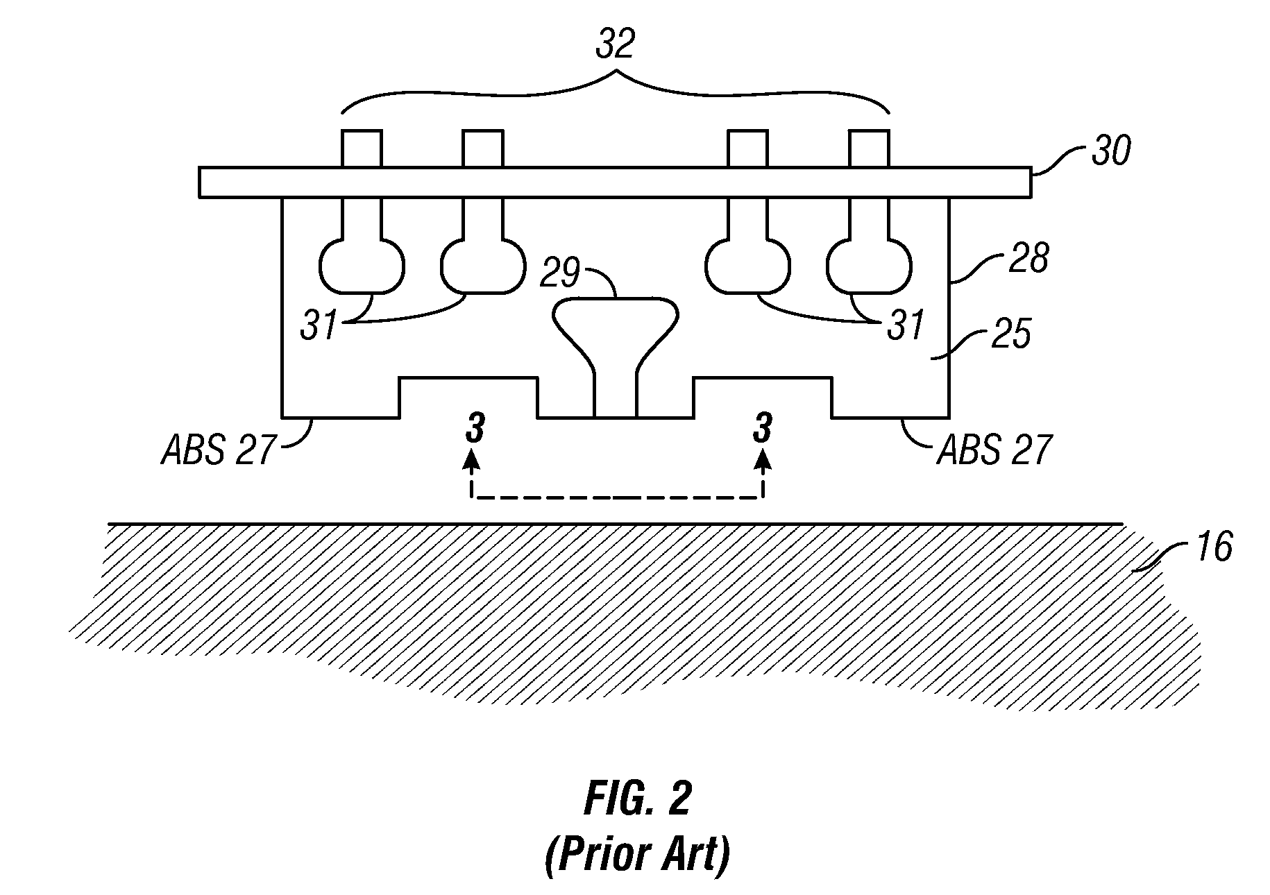
[0024]FIG. 1 is a top plan view of a head / disk assembly of a hard disk drive 10 with the cover removed. The disk drive 10 includes a rigid base 12 supporting a spindle 14 that supports a stack of disks, including top disk 16. The spindle 14 is rotated by a spindle motor (not shown) for rotating the disks in the direction shown by curved arrow 17. The hard disk drive 10 has at least one load beam assembly 20 having an integrated lead suspension (ILS) or flexure 30 with an array 32 of electrically conductive interconnect traces or lines. The load beam assemblies 20 are attached to rigid arms 22 connected to an E-shaped support structure, sometimes called an E-block 24. Each flexure 30 is attached to an air-bearing slider 28. A magnetic recording read / write head 29 is located at the end or trailing surface 25 of slider 28. The flexure 30 enables the slider 28 to “pitch” and “roll” on an air-bearing generated by the rotating disk 16. Disk drive 10 also includes a rotary actuator assembl...


PUM

PropertyMeasurementUnit
angleaaaaaaaaaa
angleaaaaaaaaaa
angleaaaaaaaaaa

Abstract

A perpendicular magnetic recording system has a write head having a main coil (the write coil) and main pole (the write pole) that directs write flux in a direction perpendicular to the recording layer in the magnetic recording medium, and a transverse auxiliary pole (TAP) that injects auxiliary magnetic flux into the write pole at an angle to the primary or perpendicular axis of the write pole. The additional flux from the TAP, which is injected non-parallel to the primary magnetization of the write pole, exerts a torque on the magnetization of the write pole, thereby facilitating magnetization reversal of the write pole. The TAP is coupled to the main coil but not electrically connected to it. A separate passive coil, not electrically connected to the main coil, may be wrapped as a loop around the main pole and the TAP. Alternatively, the TAP may be located near one of the electrically conductive turns of the main coil.

Description

BACKGROUND OF THE INVENTION[0001]1. Field of the Invention[0002]This invention relates generally to perpendicular magnetic recording systems, and more particularly to a system with fast switching of the magnetization direction of the perpendicular write head.[0003]2. Description of the Related Art[0004]Perpendicular magnetic recording, wherein the recorded bits are stored in a perpendicular or out-of-plane orientation in the recording layer, allows for ultra-high recording densities in magnetic recording hard disk drives. The write head must be able to write data not only at high bit-density but also at high data-rates. The write speed is particularly important in enterprise disk drives. However, the switching time for the main pole of the write head to switch from one magnetization direction to the other is a limiting factor as the data rate is increased. At high data-rates, the available magnetic flux from the write head, as seen by the recording layer on the disk, is dominated by...

Claims


Application Information

Patent Timeline
Patent Type & Authority Applications(United States)
IPC IPC(8): G11B15/64G11B5/33
CPCG11B5/1278G11B2005/0005G11B5/3146G11B5/3116
Inventor CONTRERAS, JOHN THOMASSCHABES, MANFRED ERNST
Owner WESTERN DIGITAL TECH INC
Why Eureka
Try Eureka