
Assembly structure for LED fixture

Inactive Publication Date: 2011-03-03
CHEN SHIH MING
View PDF9 Cites 32 Cited by
  • Summary
  • Abstract
  • Description
  • Claims
  • Application Information

AI Technical Summary

Benefits of technology

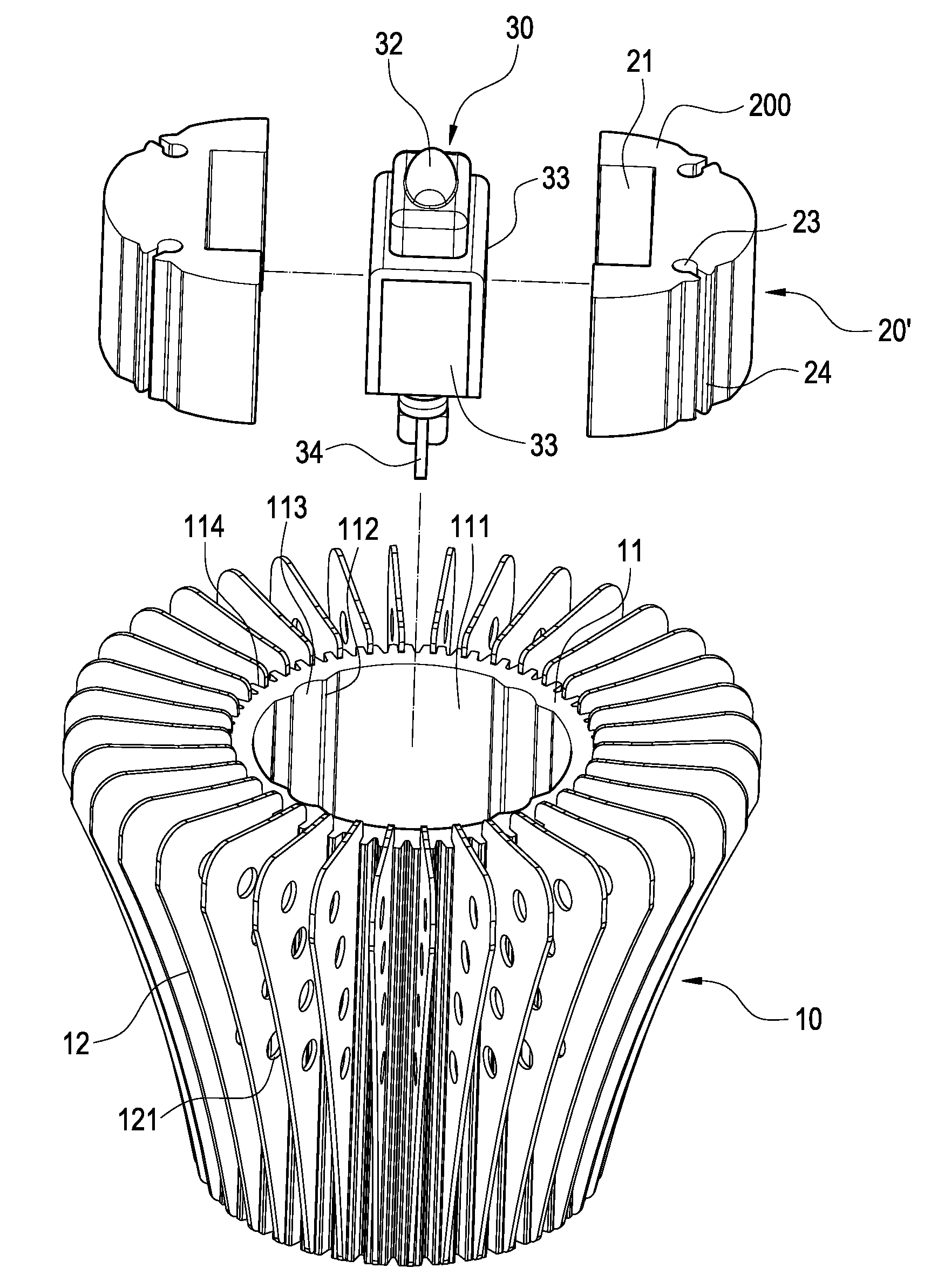
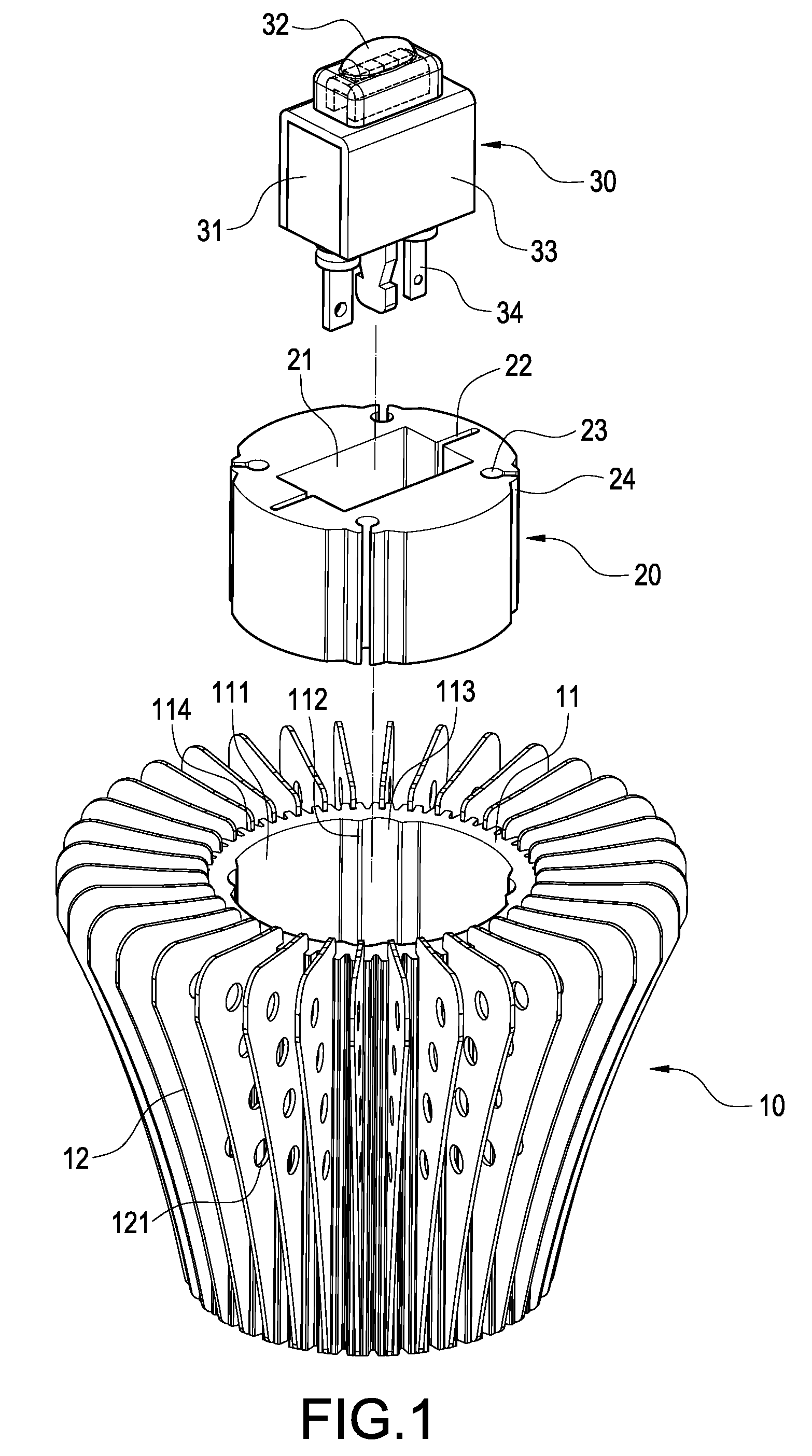
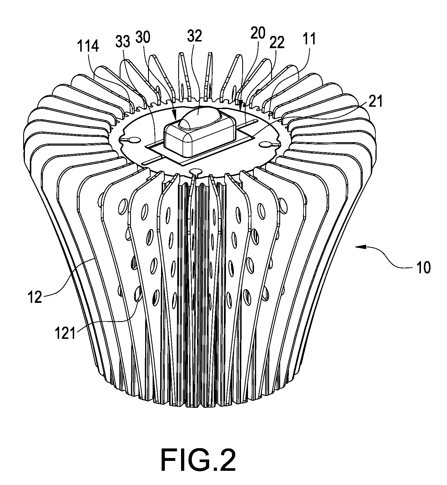
[0008]Therefore, in order to solve aforementioned problems, the invention is mainly to provide an assembly structure for LED fixture, in which a thermally conductive body can generate elastic deformations of contraction and expansion, by which the thermally conductive body is easily placed into a central hole of a cooling body, being able to achieve effects of close combination and excellent contact between each constituent components.
[0010]Thirdly, the invention is to provide an assembly structure for LED fixture, in which a thermally conductive body and an LED module are forcedly placed into a central hole of a cooling body, being able to achieve effects of close combination and excellent contact between each constituent components.
[0012]By comparing with prior arts, the invention has following functions. Since groove gaps are arranged in the thermally conductive body, it is easy for the LED module to be placed into the opening of the thermally conductive body, achieving a close combination and enhancing a thermally conductive effect between each constituent components. Furthermore, because of a wedging-and-clamping function existing between each pair of protrusive rail and position stripe, it can avoid a rotation phenomenon occurred between each other. In addition, by arranging insetting grooves separately shown as a ring shape in the cylinder, the cooling fins can be disposed in a radial and more intensive manner, thus, enhancing the cooling performance entirely.

Problems solved by technology

However, there are still a lot of drawbacks existing for this kind of LED fixture in terms of practical uses.
In order to pursue a tight (or excessive) match between the thermally conductive block and the cooling body, if insetting the thermally conductive block directly into the cooling body, not only the assembly difficulty is higher, but also a secondary machining is needed for most of the thermally conductive block or the cooling body, which derives an additional cost because of the secondary machining.
Furthermore, if it is necessary to take the thermally conductive block from the interior of the cooling body, its difficulty is even higher.
Usually, a destructive manner is needed to dismantle or separate both components.
Besides, if the bottom face of the LED is directly attached onto the thermally conductive block to undergo a thermally conductive and cooling process, it will be restricted by the limitation of contacting area, making the heat generated from the LED unable to be dissipated quickly and in large amount, which is an issue needed to be addressed urgently.

Method used


Image

  • Assembly structure for LED fixture
  • Assembly structure for LED fixture
  • Assembly structure for LED fixture

Examples


third embodiment

[0030]Please refer to FIG. 7, showing the invention. This embodiment is mainly to form a chamfer 25 at the bottom part of the thermally conductive body 20″. Since the size of this chamfer 25 is smaller than that of the central hole 111 of the cylinder 11, the chamfer 25 of the thermally conductive body 20″ can be first inset into the central hole 111. Then, a press tool (not shown in the figures) can be directly used to press down the thermally conductive body 20″ to be forcedly inset into the central hole 111 and combined therewith tightly.

fourth embodiment

[0031]Please refer to FIG. 8, showing the invention. This embodiment is mainly to design the opening 21 of the thermally conductive body 20 as a quadrilateral configuration, one width of which is approximately smaller than the width of the thermally conductive piece 33 of the LED module 30, such that a press tool can be used to squeeze the LED module 30 into the opening 21 of the thermally conductive body 20 by force, whereby both components are tightly combined.

fifth embodiment

[0032]Please refer to FIG. 9, showing the invention. This embodiment is mainly to design the opening 21 of the thermally conductive body 20 as a quadrilateral configuration as well, however, one width of which is designed to be larger than the width of the thermally conductive piece 33 of the LED module 30 such that, after the LED module 30 has been placed into the opening 21 of the thermally conductive body 20, a spacer 40 is inset into the gap formed between the LED module and the opening 21, whereby both components are tightly combined.

[0033]Accordingly, through the constitution of aforementioned assemblies, an assembly structure for LED fixture according to the invention is thus obtained.


PUM


Abstract

An assembly structure for LED fixture includes a cooling body, a thermally conductive body and an LED module. The cooling body includes a cylinder, a center of which has a central hole; the thermally conductive body is arranged an opening and a plurality of sectional grooves, each of which is elastically deformed to make the thermally conductive body forcedly arranged into the central hole and thermally contacted with the cylinder; the LED module is connected by passing through the opening of the thermally conductive body and includes a seat body, an LED fixed to the seat body and a thermally conductive piece fitted onto the seat body and thermally contacted with the thermally conductive body; thereby, they are easily placed into the central hole of the cooling body with a capability to achieve effects of close combination and excellent contact between each constituent components.

Description

BACKGROUND OF THE INVENTION[0001]1. Field of the Invention[0002]The present invention in general relates to an assembly structure, in particular, to an assembly structure for LED fixture.[0003]2. Description of Prior Art[0004]Among a variety of lighting components, since of the merits of superior lightness, longer lifespan and less power consumption, light-emitting diode (LED) has been comprehensively applied in a large amount of fixtures used indoors or outdoors. There are two critical factors deciding the winning or losing of these kinds of fixtures; namely, the consideration of cost and the solution of cooling problem. Therefore, taking these requirements as study issues, the inventor undergoes an innovative design embodied as the present invention.[0005]According to prior arts, an LED fixture mainly includes a cooling body, a thermally conductive block and an LED. The bottom face of the LED is directly attached onto the thermally conductive block, which is then interconnected wi...

Claims


Application Information

Patent Timeline
IPC IPC(8): F21V29/00
CPCF21K9/00F21V19/004F21V29/004F21V29/83F21Y2101/02F21V29/71F21V29/773F21V29/2212F21V29/89F21Y2115/10
Inventor CHEN, SHIH-MING
Owner CHEN SHIH MING
Learn More