Method and apparatus for forming a composite image

a composite image and image technology, applied in the field of composite image methods and apparatus, can solve the problems of distorted straight lines that traverse the boundaries of smaller images when stitched to form the larger image, and achieve the effect of reducing the gradient across the overlap

Active Publication Date: 2011-03-03
SONY CORP
View PDF5 Cites 37 Cited by
  • Summary
  • Abstract
  • Description
  • Claims
  • Application Information

AI Technical Summary

Benefits of technology

[0010]adjusting one of the first and second element

Problems solved by technology

However, this method has two problems.
Secondly, because the cameras capturing the smaller images can never be exactly co-loc

Method used


Image

  • Method and apparatus for forming a composite image
  • Method and apparatus for forming a composite image
  • Method and apparatus for forming a composite image

Examples


Embodiment Construction

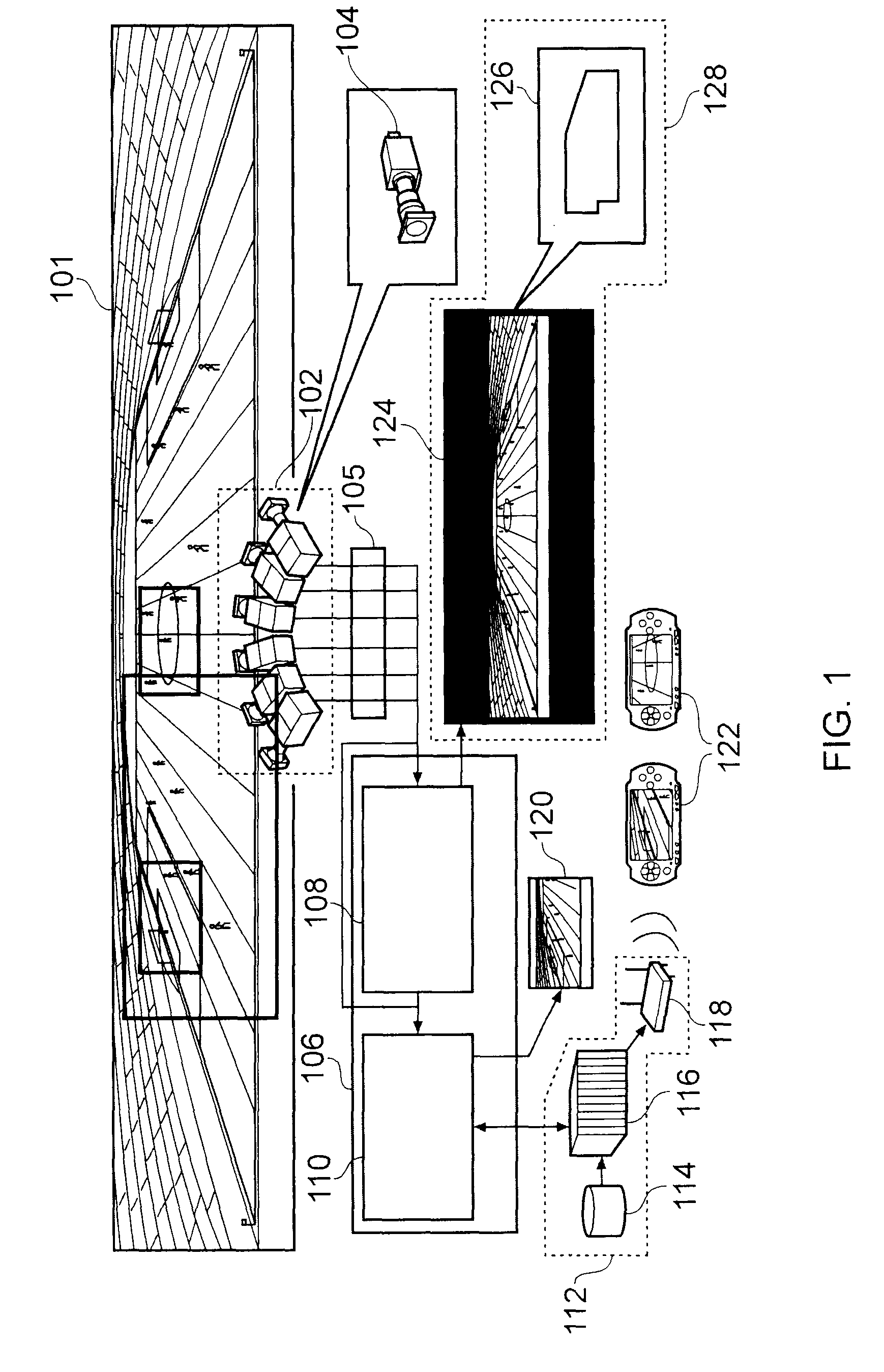
[0047]Referring to FIG. 1, the live event 101, which in this example is a soccer match is held in a venue, which in this example is a stadium.

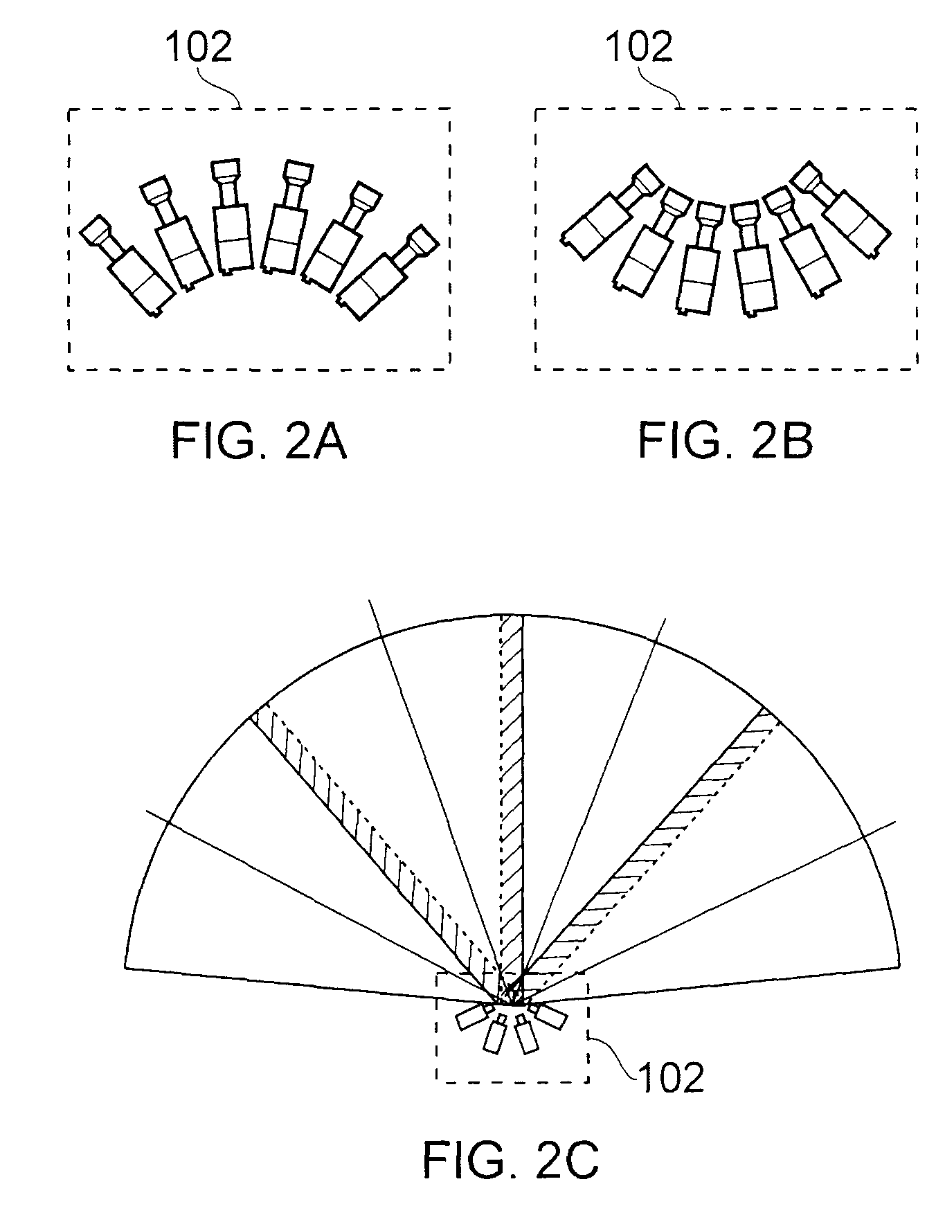
[0048]A camera cluster 102, which in this Figure consists of six individual cameras 104 arranged in a certain configuration (but in FIG. 6 consists of three individual cameras 104), is positioned at an appropriate vantage point in the stadium. The configuration of the camera cluster 102 will be explained in more detail with reference to FIGS. 2A, 2B and 2C. However, in summary, the camera cluster 102 is configured so that the field of view of each camera 104 within the camera cluster 102 overlaps to a small degree with the field of view of an adjacent camera 104 in the camera cluster 102. Thus, the entire live event is covered by panoramic view generated by the totality of the field of view of the camera cluster 102. The vantage point may be at an elevated position in the stadium.

[0049]In this embodiment, each camera 104 is a High Definition (...


PUM


Abstract

Disclosed is an apparatus for forming a composite image of a scene from a plurality of overlapping elemental images, the apparatus comprising:
    • a selector for selecting one point in one of the plurality of images and another point in a second one of the plurality of images, the first point and the other point being overlaid in the composite image and being of substantially the same point in the scene;
    • a determiner for determining, when the first point and the other point are overlaid, the gradient across the overlap between the first and other elementary image; and
    • an adjuster for adjusting one of the first and second elementary image to minimise the gradient across the overlap. A corresponding method is also disclosed.

Description

BACKGROUND OF THE INVENTION[0001]1. Field of the Invention[0002]The present invention relates to a method and apparatus for forming a composite image.[0003]2. Description of the Prior Art[0004]It is possible to form an image from a number of smaller images. Typically, these smaller images are stitched together to form the larger image. In order to do this, each smaller image must have an area of overlap with adjacent smaller images so that the larger image is continuous. In order to align the smaller images, it is known to select a large number of so-called “correspondence points” in each image. A correspondence point is a point in two adjacent smaller images which represent the same point in the scene. This assists in making the larger image appear continuous.[0005]However, this method has two problems. Firstly, in order to ensure that the smaller images are as closely aligned as possible, a large number of correspondence points are required. Specifically, it is typical that these ...

Claims


Application Information

Patent Timeline
IPC IPC(8): G06K9/60
CPCG03B37/04G06T3/4038H04N5/2628H04N5/247H04N5/23238H04N23/698H04N23/90G06T7/33H04N5/2624
Inventor PORTER, ROBERT MARK STEFAN
Owner SONY CORP
Why Eureka
Try Eureka