Turbine airfoil with outer wall cooling system and inner mid-chord hot gas receiving cavity

a cooling system and airfoil technology, applied in the field of hollow turbine airfoils, can solve the problems of reducing the mechanical life cycle of airfoils, large thermal gradient between these regions, and the likelihood of failure, so as to reduce the thermal gradient in the outer wall materials, the effect of increasing the life of the airfoil

Inactive Publication Date: 2007-12-04
SIEMENS ENERGY INC
View PDF14 Cites 62 Cited by
  • Summary
  • Abstract
  • Description
  • Claims
  • Application Information

AI Technical Summary

Benefits of technology

[0005]This invention is directed to a turbine airfoil having a cooling system in inner aspects of the turbine airfoil for use in turbine engines. The cooling system may be configured such that adequate cooling occurs within an outer wall of the turbine airfoil by including one or more cooling cavities in the outer wall and configuring each outer cooling cavity based on local external heat loads and airfoil gas side pressure distribution in both chordwise and spanwise directions. The turbine airfoil may include a hot gas receiving cavity positioned in the mid-chord region of the turbine airfoil. The hot gas receiving cavity allows hot combustion gases to flow in central aspects of the turbine airfoil to heat inner walls of the airfoil forming the hot gas receiving cavity. By heating the inner walls, the thermal gradient in the materials forming the outer wall is minimized, thereby increasing the life of the airfoil.
[0009]An advantage of this invention is that the high temperature gradient typically found within conventional airfoils having cooling cavities in the outer wall is greatly reduced in the airfoil of the instant invention due to the heating that occurs in the hot gas receiving cavity positioned in the mid-chord region of the airfoil. Introducing hot gases into the mid-chord region of the airfoil heats inner portions of the airfoil, thereby preventing the formation of extreme thermal gradients within the airfoil and increasing the life span of the airfoil.
[0010]Another advantage of this invention is that the hot gas receiving cavity creates improved TMF in the airfoil, thereby increasing the life cycle of the airfoil, as compared with conventional designs.
[0011]Yet another advantage of this invention is that the hot gas receiving cavity positioned in the central region of the airfoil eliminates the need to pressurize the airfoil mid-chord cavity. The lack of a mid-chord cooling cavity minimizes the pressure gradient between the hot gas receiving cavity and the outer wall cooling cavity, thereby increasing the efficiency of the turbine engine into which the airfoil is mounted.

Problems solved by technology

In addition, turbine vanes and blades often contain cooling systems for prolonging the life of the vanes and blades and reducing the likelihood of failure as a result of excessive temperatures.
The walls forming the pressurized mid-chord cooling channel often remain at temperatures much lower than portions of the airfoil in contact with hot combustion gases, thereby resulting in a large thermal gradient between these regions.
The large thermal gradient often results in a reduced mechanical life cycle of airfoil components and poor thermal mechanical fatigue (TMF).
Therefore, the inner cooling channel often negatively affects the life cycle of the airfoil.

Method used


Image

  • Turbine airfoil with outer wall cooling system and inner mid-chord hot gas receiving cavity
  • Turbine airfoil with outer wall cooling system and inner mid-chord hot gas receiving cavity
  • Turbine airfoil with outer wall cooling system and inner mid-chord hot gas receiving cavity

Examples


Embodiment Construction

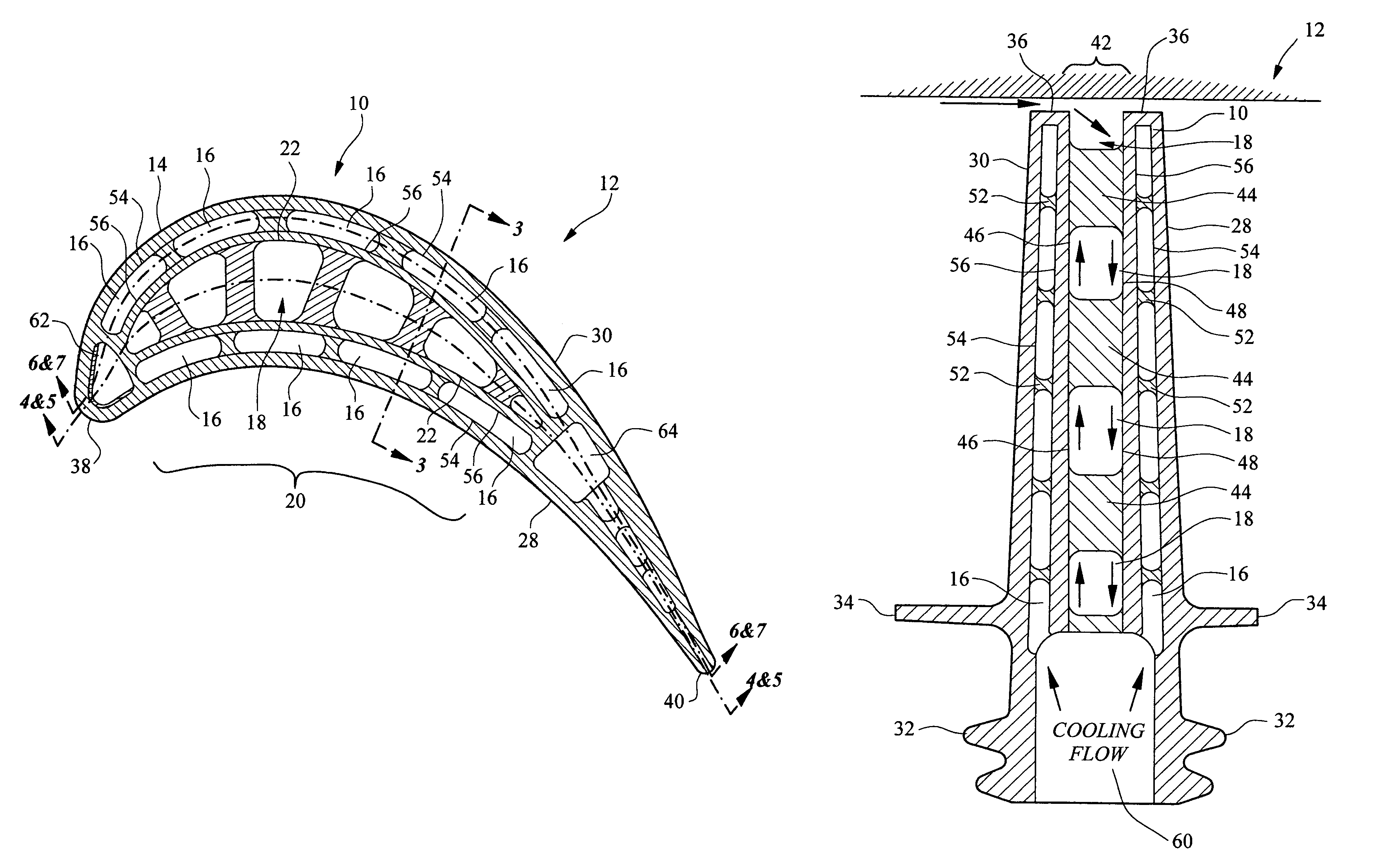
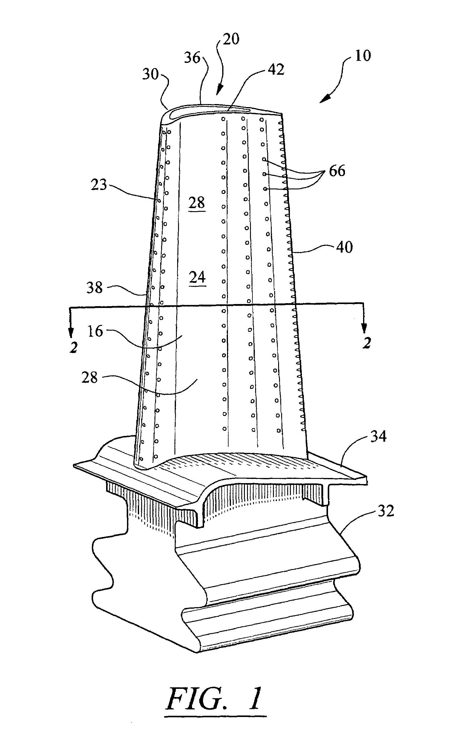
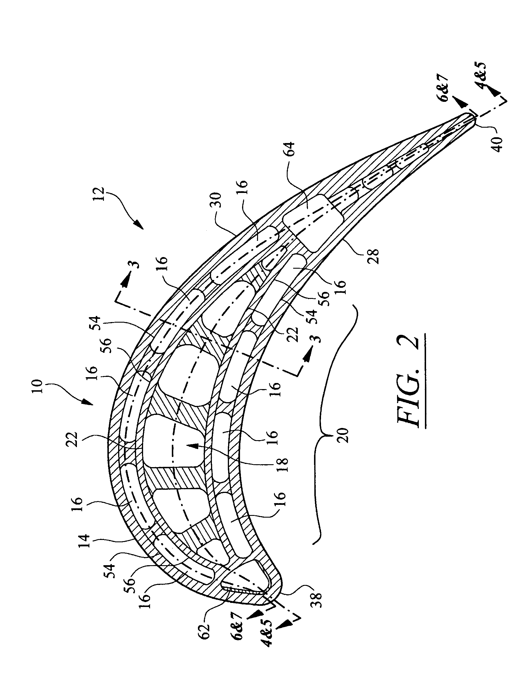
[0021]As shown in FIGS. 1-7, this invention is directed to a turbine airfoil 10 having a cooling system 12 in inner aspects of the turbine airfoil 10 for use in turbine engines. The cooling system 12 may be configured such that adequate cooling occurs within an outer wall 14 of the turbine airfoil 10 by including one or more cavities 16 in the outer wall 14 and configuring each outer cooling cavity 16 based on local external heat loads and airfoil gas side pressure distribution in both chordwise and spanwise directions. The chordwise direction is defined as extending between a leading edge 38 and a trailing edge 40 of the airfoil 10, and the spanwise direction is defined as extending between a tip 36 of the airfoil 10 and a root 32. The turbine airfoil 10 may include a hot gas receiving cavity 18, as shown in FIG. 3, positioned in the mid-chord region 20 of the turbine airfoil 10. The hot gas receiving cavity 18 allows hot combustion gases to flow into central aspects of the turbine...


PUM


Abstract

A turbine airfoil usable in a turbine engine and having at least one cooling system. The cooling system may be positioned in an outer wall of the turbine airfoil, and the airfoil may include a hot gas receiving cavity positioned in a mid-chord region of the airfoil. The hot gas receiving cavity may have an opening in a tip of the airfoil to enable hot gases to circulate into the hot gas receiving cavity. In at least one embodiment, the cooling system in the outer wall and the hot gas receiving cavity may include a plurality of ribs. Cooling fluids may be passed through the cooling system in the outer wall, and hot combustion gases may be passed into the hot gas receiving cavity to moderate the temperature of the inner portions of the outer wall to reduce the temperature gradient in the outer wall.

Description

FIELD OF THE INVENTION[0001]This invention is directed generally to turbine airfoils, and more particularly to hollow turbine airfoils having cooling channels for passing fluids, such as air, to cool the airfoils.BACKGROUND[0002]Typically, gas turbine engines include a compressor for compressing air, a combustor for mixing the compressed air with fuel and igniting the mixture, and a turbine blade assembly for producing power. Combustors often operate at high temperatures that may exceed 2,500 degrees Fahrenheit. Typical turbine combustor configurations expose turbine vane and blade assemblies to these high temperatures. As a result, turbine vanes and blades must be made of materials capable of withstanding such high temperatures. In addition, turbine vanes and blades often contain cooling systems for prolonging the life of the vanes and blades and reducing the likelihood of failure as a result of excessive temperatures.[0003]Typically, turbine airfoils are formed from an elongated p...

Claims


Application Information

Patent Timeline
Patent Type & Authority Patents(United States)
IPC IPC(8): F01D5/18
CPCF01D5/187
Inventor LIANG, GEORGE
Owner SIEMENS ENERGY INC
Why Eureka
Try Eureka