Ceiling fan

Inactive Publication Date: 2011-03-03
PANASONIC CORP
View PDF8 Cites 22 Cited by
  • Summary
  • Abstract
  • Description
  • Claims
  • Application Information

AI Technical Summary

Benefits of technology

[0007]Such a ceiling fan has a suspension device provided with two movable connecting portions between a connecting fitting fixed to a ceiling and a ceiling fan main body. Therefore, the transmission of the vibration of the ceiling fan main body during operation is reduced by the two movable connecting portions. Furthermore, the swing of the ceiling

Problems solved by technology

Furthermore, the swing of the ceiling fan main body during operat

Method used


Image

  • Ceiling fan
  • Ceiling fan
  • Ceiling fan

Examples


Example

First Exemplary Embodiment

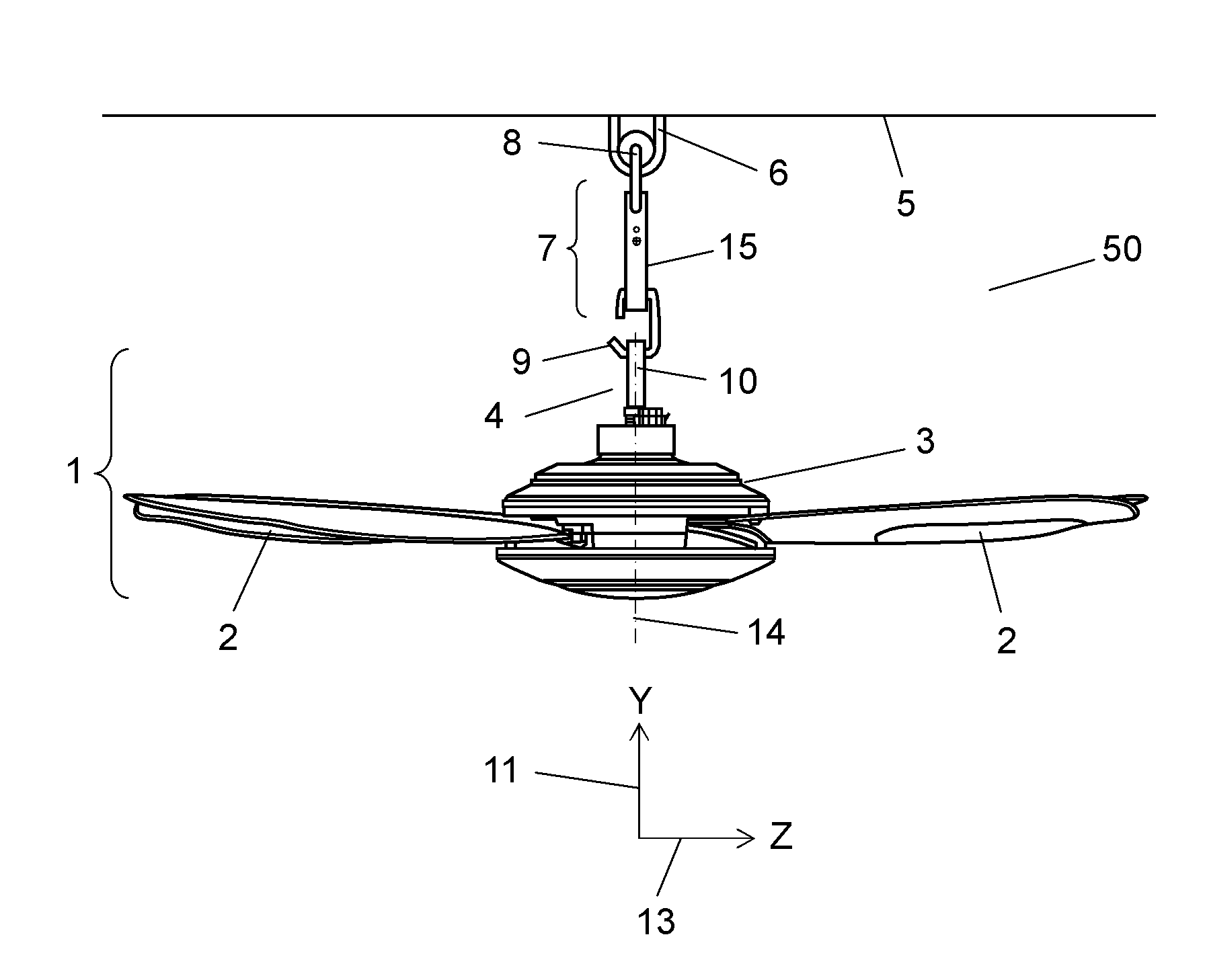
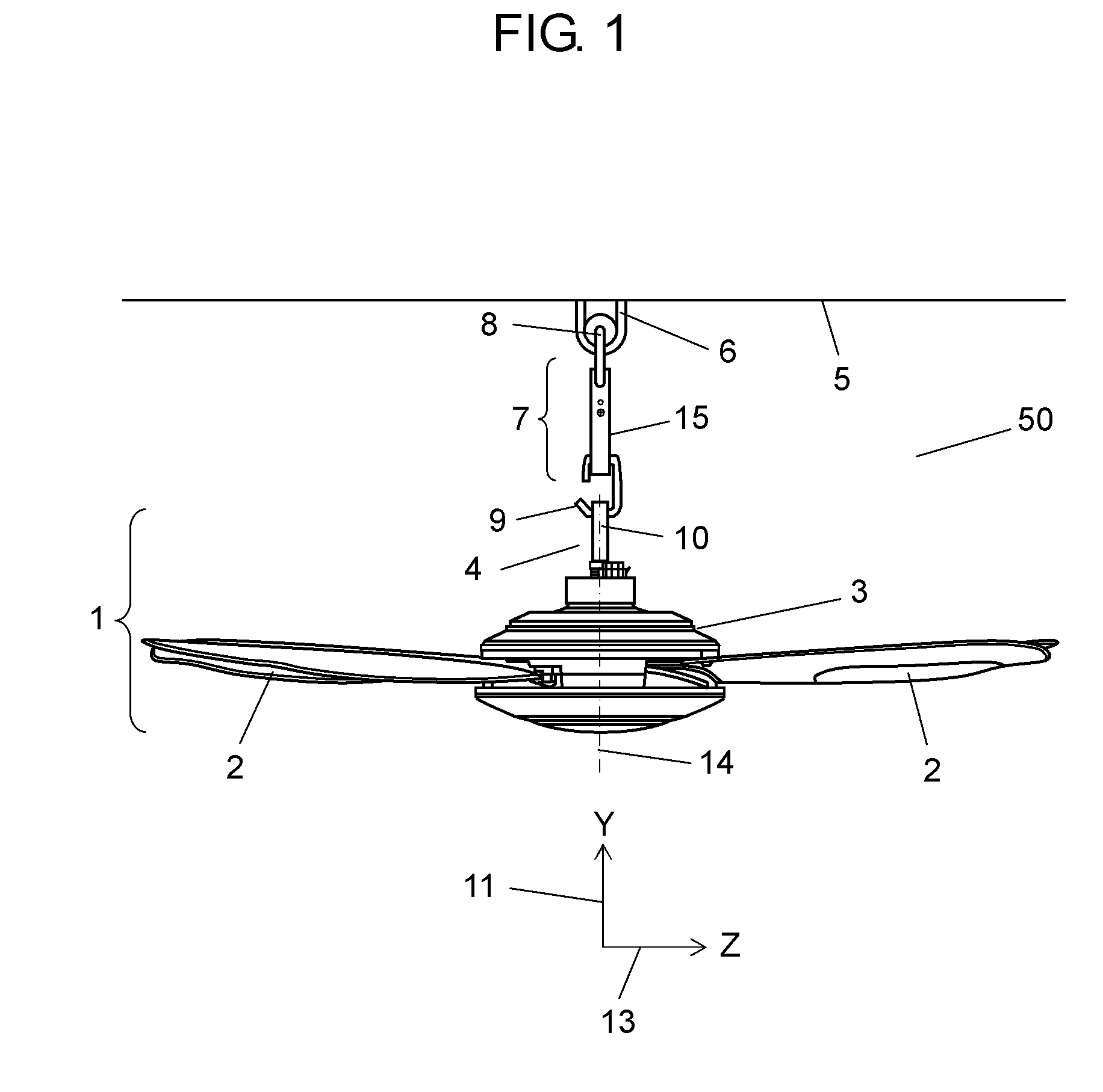
[0019]FIG. 1 is a side view showing a ceiling fan in accordance with a first exemplary embodiment of the present invention; FIG. 2 is a perspective view showing the ceiling fan. Ceiling fan 50 includes connecting fitting 6, suspension device 7, and ceiling fan main body 1. Herein, connecting fitting 6 is fixed to ceiling 5. Ceiling fan main body 1 is suspended from connecting fitting 6 via suspension device 7.

[0020]Suspension device 7 includes a first connecting portion including horizontal axis connecting portion 8 and a second connecting portion including horizontal axis connecting portion 9. Herein, the first connecting portion can be movably mounted on connecting fitting 6. The second connecting portion is located in the lower part of the first connecting portion.

[0021]Ceiling fan main body 1 includes motor 3, shaft 4, and joint portion 10. Herein, motor 3 rotates a plurality of blades 2 attached in the horizontal direction. Shaft 4 protrudes to the upp...

Example

Second Exemplary Embodiment

[0027]In accordance with a second exemplary embodiment of the present invention, the same reference numerals are given to the same elements as in the first exemplary embodiment and the description thereof is omitted, and only different configuration is described. The second exemplary embodiment of the present invention and the first exemplary embodiment are different from each other in a configuration of a second connecting portion.

[0028]FIG. 3 is a side view showing a ceiling fan in accordance with the second exemplary embodiment of the present invention. FIG. 4 is a perspective view showing the ceiling fan. FIG. 5 is an enlarged view showing a principal part of a suspension device of the ceiling fan.

[0029]Suspension device 37 of ceiling fan 51 includes a first connecting portion including horizontal axis connecting portion 8, and a second connecting portion holding horizontal plane axis connecting portion 16. The first connecting portion is rotatable in ...

Example

Third Exemplary Embodiment

[0040]In accordance with a third exemplary embodiment of the present invention, the same reference numerals are given to the same elements as in the first exemplary embodiment and the description thereof is omitted, and only different configurations are described. The third exemplary embodiment of the present invention and the first exemplary embodiment are different from each other in a configuration of a first connecting portion.

[0041]FIG. 6 is a side view showing a ceiling fan in accordance with the third exemplary embodiment of the present invention. Suspension device 47 of ceiling fan 52 includes a first connecting portion that is horizontal plane axis connecting portion 23 and a second connecting portion that is horizontal axis connecting portion 9. The first connecting portion is rotatable around a rotation axis on the horizontal plane including X-axis 12 and Z-axis 13. The second connecting portion is rotatable in the direction of X-axis 12 as a rot...


PUM


Abstract

A ceiling fan including a connecting fitting fixed to a ceiling, and a ceiling fan main body suspended from the connecting fitting via a suspension device. The ceiling fan main body includes a motor for rotating a plurality of blades attached in a horizontal direction, a shaft protruding to an upper part of the motor, and a joint portion fixed on an upper part of the shaft. The suspension device includes a first connecting portion capable of being movably mounted on the connecting fitting, and a second connecting portion located in a lower part of the first connecting portion. The joint portion is movably mounted on the second connecting portion.

Description

TECHNICAL FIELD[0001]The present invention relates to a ceiling fan suspended from a ceiling.BACKGROUND ART[0002]A conventional ceiling fan includes a connecting fitting fixed to a ceiling, and a ceiling fan main body suspended from the connecting fitting via a suspension device.[0003]When such a ceiling fan is operated in a state in which it is suspended from a ceiling, a ceiling fan main body may occasionally swing. That is to say, in a conventional ceiling fan, a shaft protruding from the upper part of the ceiling fan main body is movably anchored to the connecting fitting fixed to a ceiling. However, not-specified swing components in all directions are generated due to vane weight and unbalanced pitch in a ceiling fan, circulation air generated during operation of a ceiling fan main body, outside wind, and the like, causing a ceiling fan main body to swing non-constantly.[0004]In such circumstances, conventionally, in order to suppress swing, a ceiling fan main body is firmly fi...

Claims


Application Information

Patent Timeline
IPC IPC(8): F04D29/00
CPCF04D25/08
Inventor YAMAMOTO, KIMINOBUKAWAZU, TETSUJIYOSHIKAWA, HIROSHIIWAMOTO, KIYOHIKO
Owner PANASONIC CORP
Why Eureka
Try Eureka