Rechargeable battery

a rechargeable battery technology, applied in the field of rechargeable batteries, can solve the problems of increasing internal pressure, battery may explode or combust, and it is difficult to have a structure that cuts off or discharges current, and achieves the effect of improving safety

Active Publication Date: 2011-03-03
ROBERT BOSCH GMBH +1
View PDF62 Cites 95 Cited by
  • Summary
  • Abstract
  • Description
  • Claims
  • Application Information

AI Technical Summary

Benefits of technology

[0011]An aspect of an embodiment of the present invention is directed toward a rechargeable battery having improved safety.

Problems solved by technology

When excessive heat is generated inside a rechargeable battery, or electrolyte solution is decomposed, increasing the internal pressure, the battery may explode or combust.
Particularly, in a prismatic battery, due to its unique terminal structure, it is difficult to have a structure that cuts off or discharges current, especially when compared to a cylindrical battery.

Method used


Image

  • Rechargeable battery
  • Rechargeable battery
  • Rechargeable battery

Examples


first embodiment

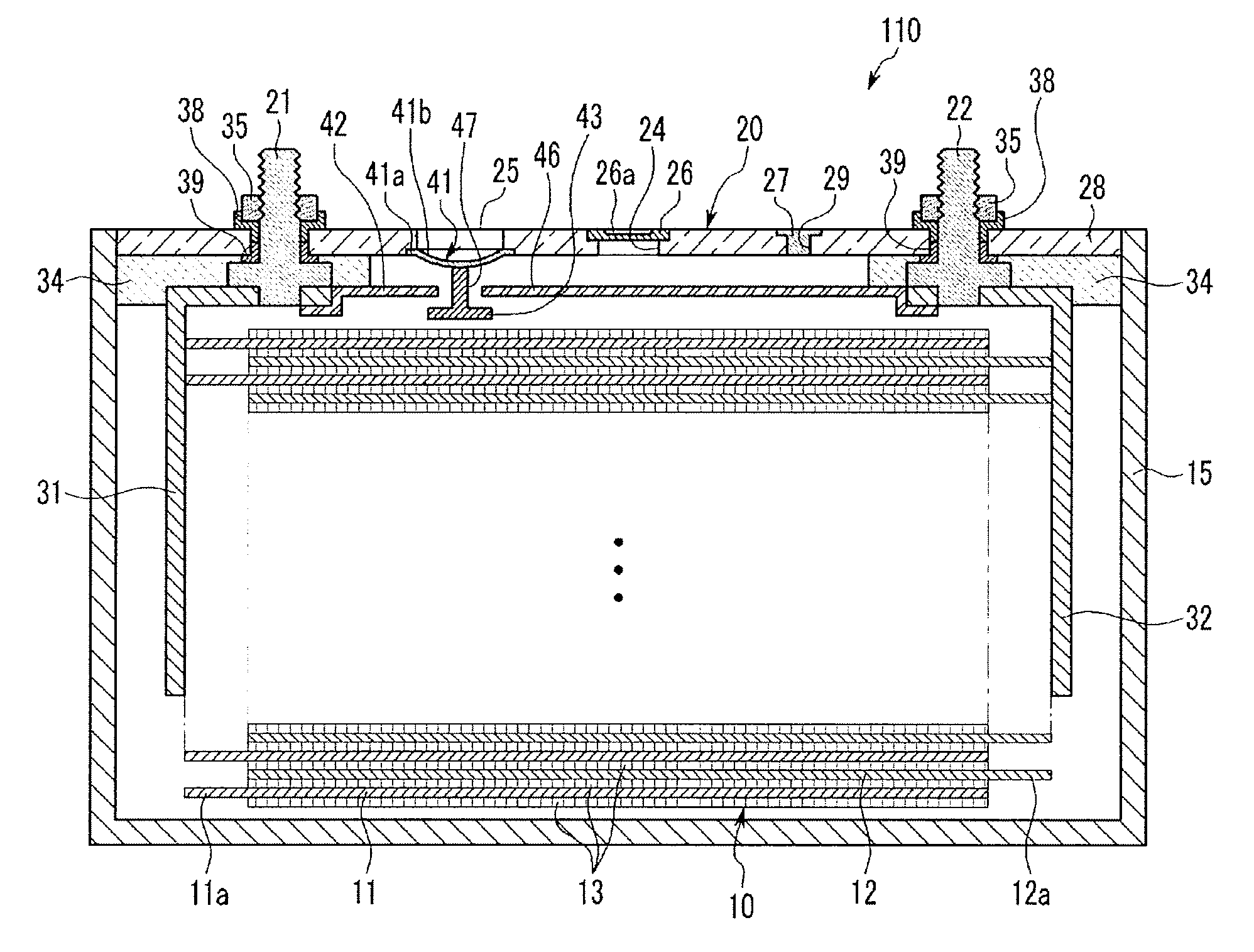
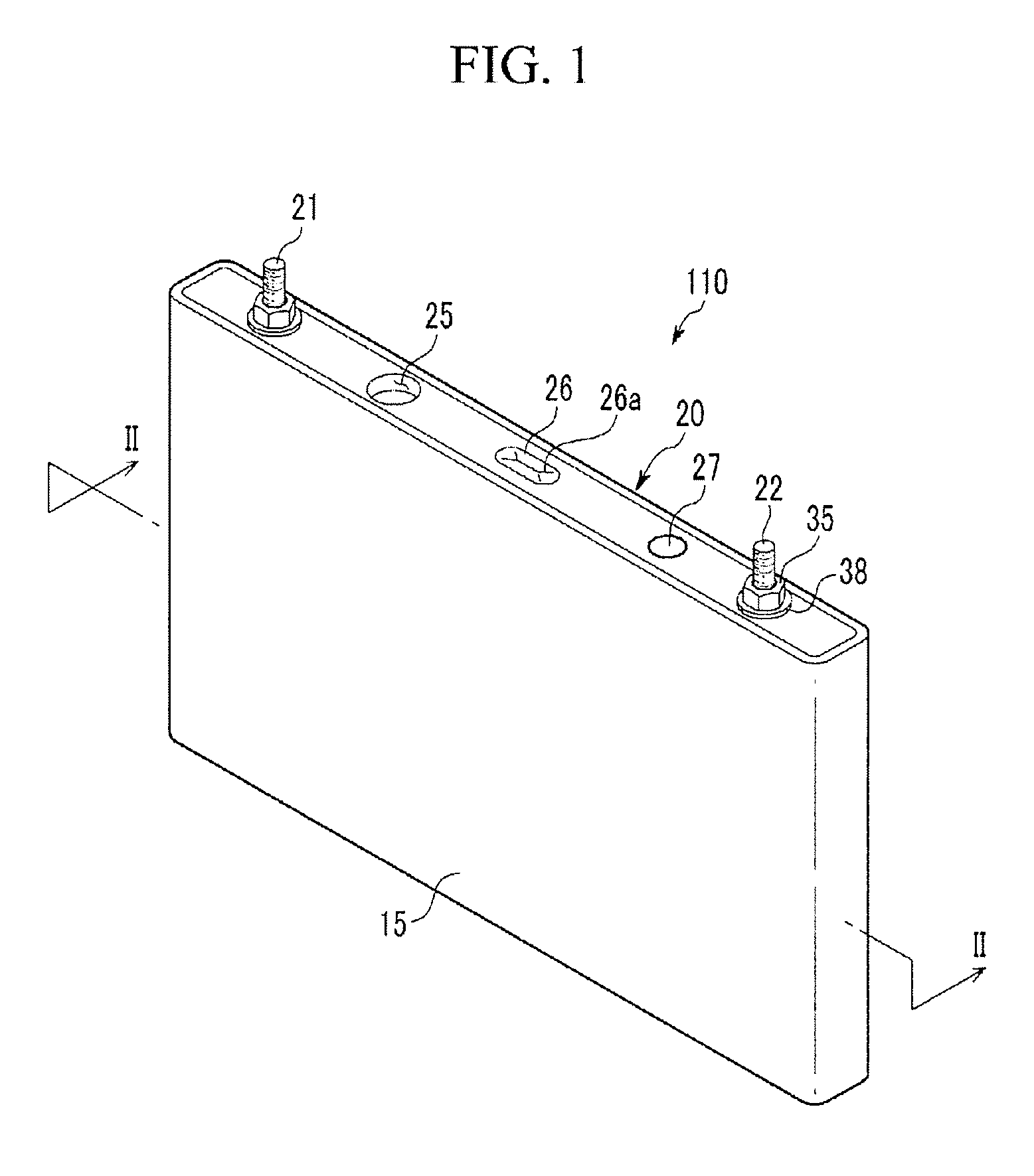
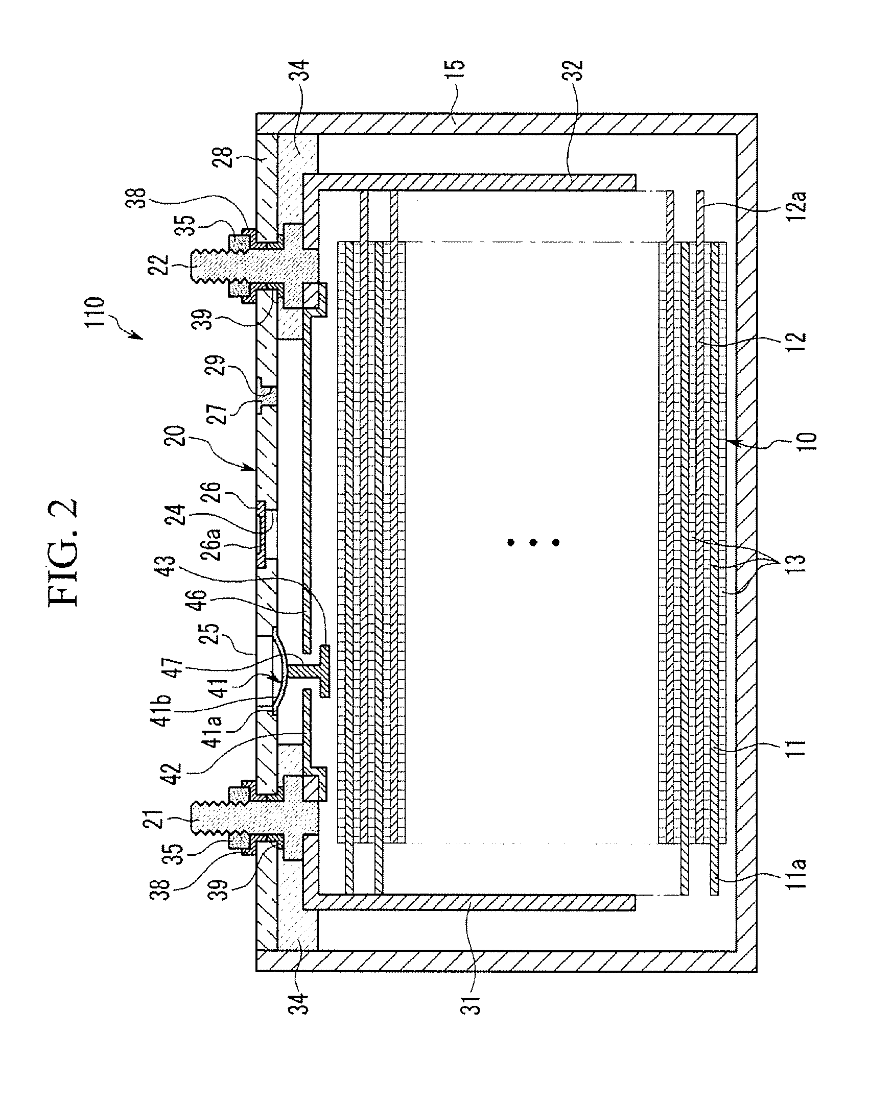
[0029]The rechargeable battery 110 is a prismatic lithium ion rechargeable battery. However, the present invention is not limited thereto, and the present invention may be applied to various types of batteries such as a lithium polymer battery or a cylindrical lithium ion secondary battery.

[0030]The first electrode 11 and the second electrode 12 include coated regions, where active material is coated on a current collector formed of a thin plate of a metal foil, and uncoated regions 11a and 12a, where the active material is not coated. According to the present exemplary embodiment, the first electrode 11 is a positive electrode, and the second electrode 12 is a negative electrode. However, the present invention is not limited thereto. Therefore, the first electrode 11 may be a negative electrode, and the second electrode 12 may be a positive electrode.

[0031]The uncoated region 11a of first electrode is formed on one side end of the first electrode 11 along a length direction of the...

second embodiment

[0052]FIG. 3 is a cross-sectional view of a rechargeable battery according to the present invention.

[0053]Referring to FIG. 3, the rechargeable battery 120 according to another embodiment has generally the same structure as in the rechargeable battery cell according to the first embodiment, except for the structure of tabs and intermediate member, and therefore, structures that are similar may not be further described.

[0054]As shown in FIG. 3, the rechargeable battery cell 120 according to the present exemplary embodiment includes an electrode assembly 10, a case 15 containing the electrode assembly 10, and a cap assembly 50 sealing the case 15. The cap assembly 50 includes a cap plate 28 coupled to the opening of the case 15, a first terminal 21 electrically connected to the first electrode 11 and a second terminal 22 electrically connected to the second electrode 12.

[0055]The cap plate 28 is a thin plate and has a short-circuit hole 25.

[0056]A first tab 52 is electrically connecte...

third embodiment

[0064]FIG. 4 is a cross-sectional view of a rechargeable battery according to the present invention.

[0065]The rechargeable battery 130 according to the third exemplary embodiment includes an electrode assembly 10, a case containing the electrode assembly 10, and a cap assembly 60 sealing the case 15. The cap assembly 60 includes a cap plate 28 coupled to an opening of case 15, a first terminal 21 electrically connected to the first electrode 11, and a second terminal 22 electrically connected to the second electrode 12.

[0066]The cap plate 28 is a thin plate and has a short-circuit hole 25.

[0067]A first tab 67 located above the short-circuit hole 25 is electrically connected with the first terminal 21.

[0068]The first tab 67 has a plate shape and is located above the cap plate 28. The first terminal 21 is inserted in the hole of first tab 67 and fixed by a nut 35, thus joining the first tab 67 with the first terminal 21. Thereby, the first tab 67 is electrically connected to the first...


PUM

PropertyMeasurementUnit
thicknessaaaaaaaaaa
thicknessaaaaaaaaaa
pressureaaaaaaaaaa

Abstract

A rechargeable battery includes an electrode assembly including a first electrode, a second electrode, and a separator between the first and second electrodes; a case housing the electrode assembly; and a cap assembly connected to the case. The cap assembly includes a first tab electrically connected to the first electrode, a second tab electrically connected to the second electrode, an deformable plate capable of electrically connecting the first tab and the second tab by being deformed due to a pressure increase, and an intermediate member formed between the first tab and the deformable plate.

Description

CROSS-REFERENCE TO RELATED APPLICATIONS[0001]This application claims priority to and the benefit of U.S. Provisional Application No. 61 / 238,965, filed on Sep. 1, 2009 in the United States Patent and Trademark Office, the entire content of which is incorporated herein by reference.BACKGROUND[0002]1. Field[0003]This following description relates to a rechargeable battery.[0004]2. Description of the Related Art[0005]A rechargeable battery can be recharged and discharged, unlike a primary battery that is not designed to be recharged. A low capacity rechargeable battery is used for a small portable electronic device such as a mobile phone, a laptop computer, and a camcorder, and a large capacity rechargeable battery is used as a power source for driving a motor such as for a hybrid vehicle.[0006]A large capacity high power rechargeable battery with high energy density using a non-aqueous electrolyte has been developed. The rechargeable battery is formed with a large capacity high power r...

Claims


Application Information

Patent Timeline
Patent Type & Authority Applications(United States)
IPC IPC(8): H01M2/00H01M50/147H01M50/574
CPCH01M2/043H01M2/0473H01M2/34H01M2/345Y02E60/12H01M10/0565H01M2200/20Y02T10/7011H01M10/0525Y02E60/10H01M50/147H01M50/15H01M50/578H01M50/574H01M50/148H01M50/531H01M50/155H01M50/159H01M50/169H01M50/59Y02T10/70
Inventor BYUN, SANG-WONKIM, YONG-SAMKIM, HYO-SEOBKIM, SUNG-BAEAHN, BYUNG-KYU
Owner ROBERT BOSCH GMBH
Why Eureka
Try Eureka