
Systems and methods for twisting an expansion element of a cryoablation system

a cryoablation system and expansion element technology, applied in the field of cryoablation systems, can solve problems such as the expansion element to twis

Active Publication Date: 2011-03-03
BOSTON SCI SCIMED INC
View PDF9 Cites 6 Cited by
  • Summary
  • Abstract
  • Description
  • Claims
  • Application Information

AI Technical Summary

Benefits of technology

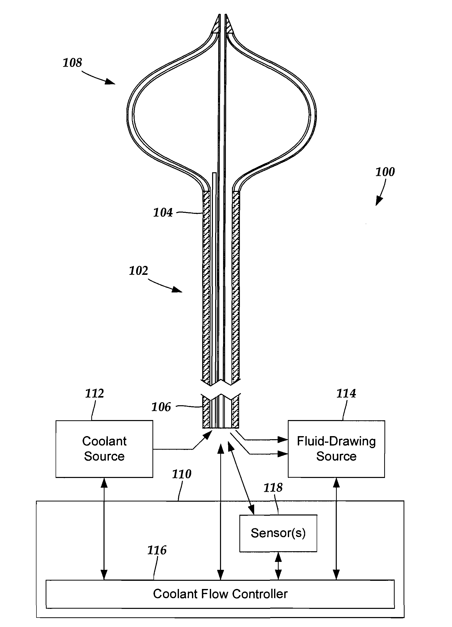
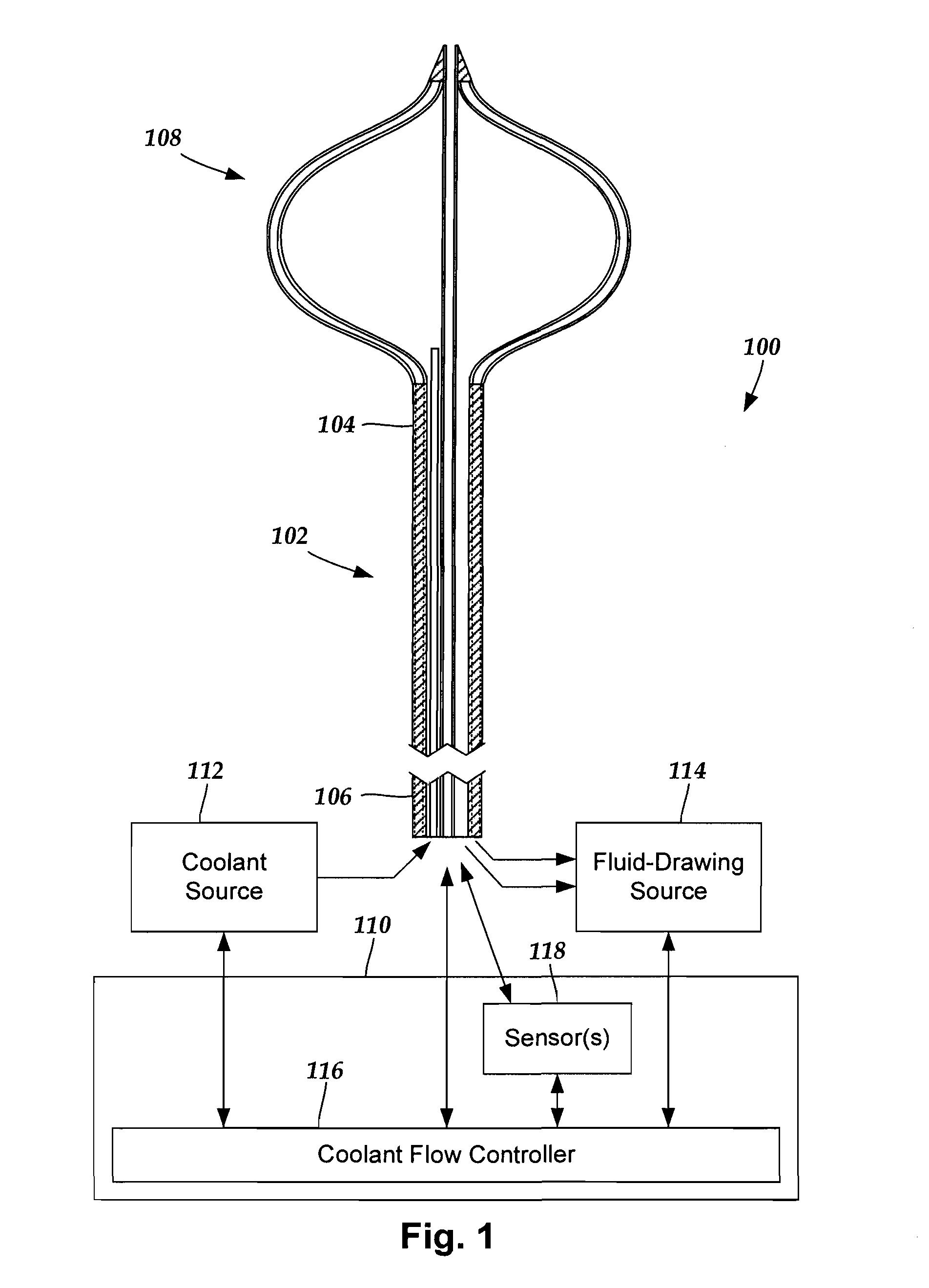
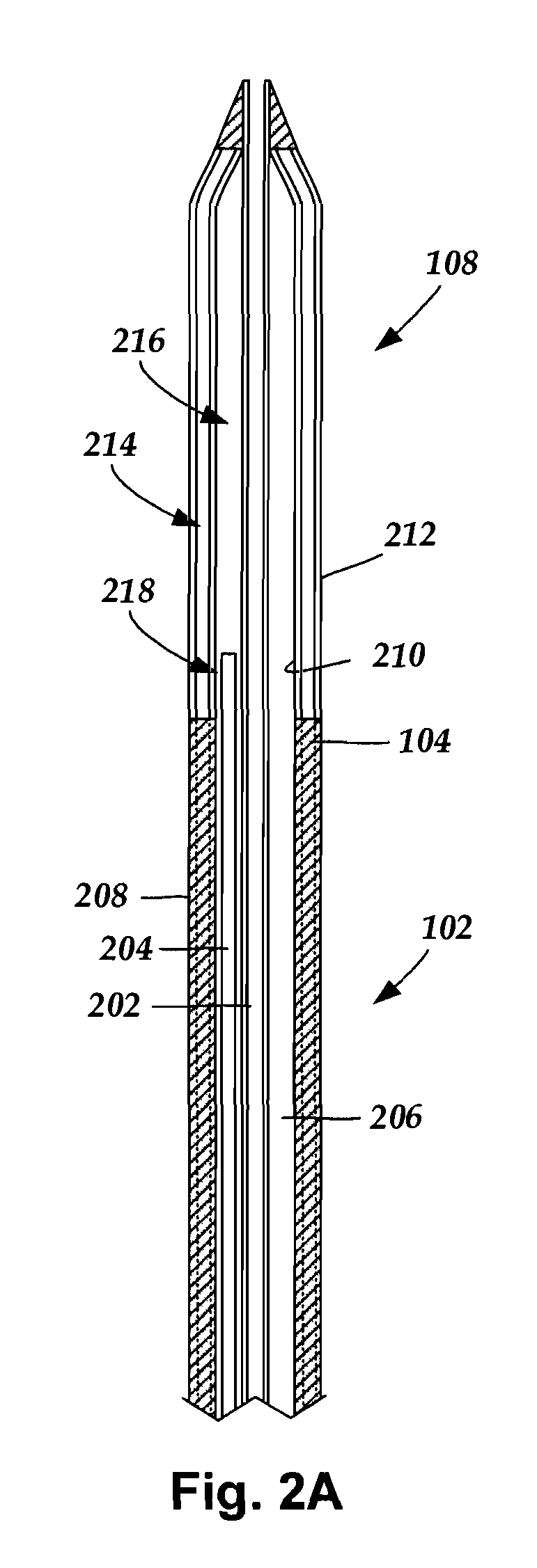
[0006]In yet another embodiment, a method for cryoablating patient tissue includes inserting a catheter in patient vasculature. The catheter has a distal portion, a proximal portion, and a longitudinal length. The catheter includes a body and defines at least one coolant outtake region. The catheter receives a guide tube and a coolant transfer tube that each extend along at least a portion of the catheter. The guide tube extends beyond the distal portion of the catheter. The catheter is guided in proximity to patient tissue to be ablated. Coolant is drawn from a coolant source such that coolant flows along the coolant transfer tube and is sprayed into an expansion element that is disposed at the distal portion of the catheter, thereby expanding the expansion element and reducing the temperature of the expansion element to a temperature sufficiently low enough to ablate patient tissue upon contact. A distal end of the expansion element is coupled to the guide tube and a proximal end of the expansion element is coupled to the body of the catheter. Patient tissue is contacted with the expanded expansion element for a time period adequate to ablate tissue contacting the expansion element. The expansion element is deflated by drawing the coolant along the at least one coolant outtake region from the expansion element. A proximal end of the guide tube is rotated in relation to the catheter using a coupled rotation system. The rotation system includes a linear gear assembly coupled to a rotational gear assembly. The rotation of the guide tube causes the distal end of the expansion element to rotate, thereby causing the expansion element to twist.

Problems solved by technology

The rotation of the guide tube causes the distal end of the expansion element to rotate, thereby causing the expansion element to twist.

Method used


Image

  • Systems and methods for twisting an expansion element of a cryoablation system
  • Systems and methods for twisting an expansion element of a cryoablation system
  • Systems and methods for twisting an expansion element of a cryoablation system

Examples


Embodiment Construction

[0019]The present invention is directed to the area of cryoablation systems and methods of making and using the systems. The present invention is also directed to cryoablation systems that include a rotation system configured and arranged for twisting an expansion element of a cryoablation system, as well as systems and methods of making and using the rotation systems, expansion elements, expansion elements, and cryoablation systems.

[0020]A cryoablation system can include a catheter configured and arranged for transporting coolant to and from a target location within a patient, an expansion element disposed at a distal portion of the catheter for ablating contacted patient tissue, a coolant source coupled to the catheter for supplying the coolant, and a control module for controlling or monitoring one or more of the operations of the system (e.g., controlling coolant flow, monitoring catheter pressure or temperature, or the like). The expansion element can be positioned at a target ...


PUM


Abstract

A cryoablation catheter assembly includes a catheter that defines at least one coolant outtake region and receives a rotatable guide tube and a coolant transfer tube. The coolant transfer tube receives and transfers coolant from a coolant source to a distal end of the coolant transfer tube. An expansion element is coupled to a distal portion of the catheter and defines an inner expansion-element space. The inner expansion-element space is in fluid communication with the at least one coolant outtake region and the distal end of the coolant transfer tube. A distal end of the expansion element couples to the guide tube. A rotation system is coupleable to, or coupled to, a proximal end of the guide tube and rotates the distal end of the expansion element relative to the proximal end of the expansion element by rotating the guide tube relative to the catheter.

Description

RELATED APPLICATIONS[0001]This application claims the benefit of U.S. Provisional Application Ser. No. 61 / 238,998, filed Sep. 1, 2009, the entire disclosure of which is incorporated herein by reference.TECHNICAL FIELD[0002]The present invention is directed to the area of cryoablation systems and methods of making and using the systems. The present invention is also directed to cryoablation systems that include a rotation system configured and arranged for twisting an expansion element of a cryoablation system, as well as systems and methods of making and using the rotation systems, expansion elements, and cryoablation systems.BACKGROUND[0003]Cryoablation systems have been used to reduce, or even eliminate, undesired electrical activity between adjacent cardiac tissues of the heart (arrhythmias). One common type of arrhythmia, atrial fibrillation, is a result of abnormal electrical signals interfering with the normal electrical signal propagation along the tissues of the heart. Atria...

Claims


Application Information

Patent Timeline
Patent Type & Authority Applications(United States)
IPC IPC(8): A61B18/02
CPCA61B18/02A61B2018/0022A61B2018/00214A61B2018/00202A61B2018/0212
Inventor CHUN, BYRON
Owner BOSTON SCI SCIMED INC
Learn More