Patient transfer device

a patient and device technology, applied in the field of patient transfer devices, can solve the problems of affecting the patient's comfort, affecting the comfort of patients, and affecting the comfort of patients, and achieve the effect of enhancing infection control and lowering air flow

Active Publication Date: 2011-03-10
STRYKER CORP
View PDF38 Cites 34 Cited by
  • Summary
  • Abstract
  • Description
  • Claims
  • Application Information

AI Technical Summary

Benefits of technology

[0008]Accordingly, the present invention provides a transfer mat that is adapted to transfer a patient using an air film and configured so that it can be operated at a significantly lower air flows than associated with prior art air bearing pallets. The mat also may be configured to provide enhanced infection control.

Problems solved by technology

Non-ambulatory patients in a patient facility, such as a hospital or a nursing home, present substantial challenges when such patients must be moved from one location to another.
The same challenge of moving a patient with minimum handling exists in non-surgical settings as well.
When such a patient is obese, transfers present difficulties for both the patient and the care facility staff.
A drawback to some current patient handling procedures, such as sliding the patient across the patient support surface, is that, even with the best intentioned and caring of staff, the patient very often suffers substantial discomfort.
The simple act of sliding a patient over a flat surface can be very painful to a patient who has had surgical incisions that are not yet healed, for example, or for patients who have skin lesions or ulcers.
A problem common to most of such devices, however, is that invariably the air mattress has the general characteristic of a balloon in the sense that when one area is indented another remote area will bulge.
Further, they tend to provide little lateral stability.
If, for example, a stretcher carrying an obese person makes a sharp turn during a trip to or from a treatment location, such an obese person may tend to roll or shift laterally toward the edge of the mattress, which could result in a patient rolling off the mattress.
Further, these mattresses require a large volume of air and flow rate to keep them inflated and operational.
They also take time to fill and to become operational given their large volumes.
Hence, to speed up the process the blowers that inflate the mattresses tend to be large and produce a lot of noise and also another undesirable by-product—heat.
If the air into the mattress is too warm, the patient can become uncomfortable.
These air pallets also tend to be bulky and may create a cleaning challenge because if body fluids (liquids) are released and flow under the mattress the holes in the bottom of the mattress will allow the liquid to flow into the mattress—likely requiring the disposal of the mattress.

Method used


Image

  • Patient transfer device
  • Patient transfer device
  • Patient transfer device

Examples


Embodiment Construction

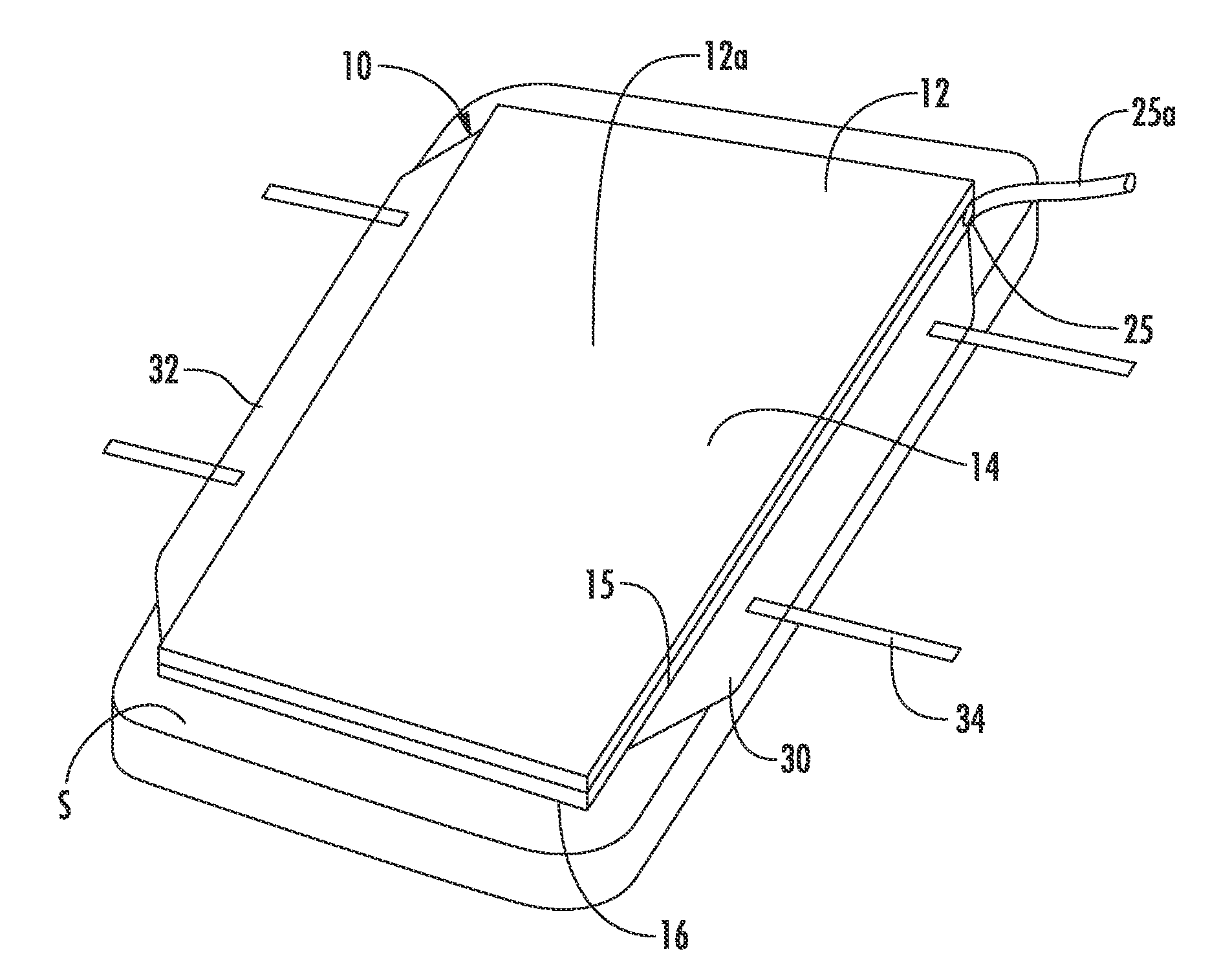
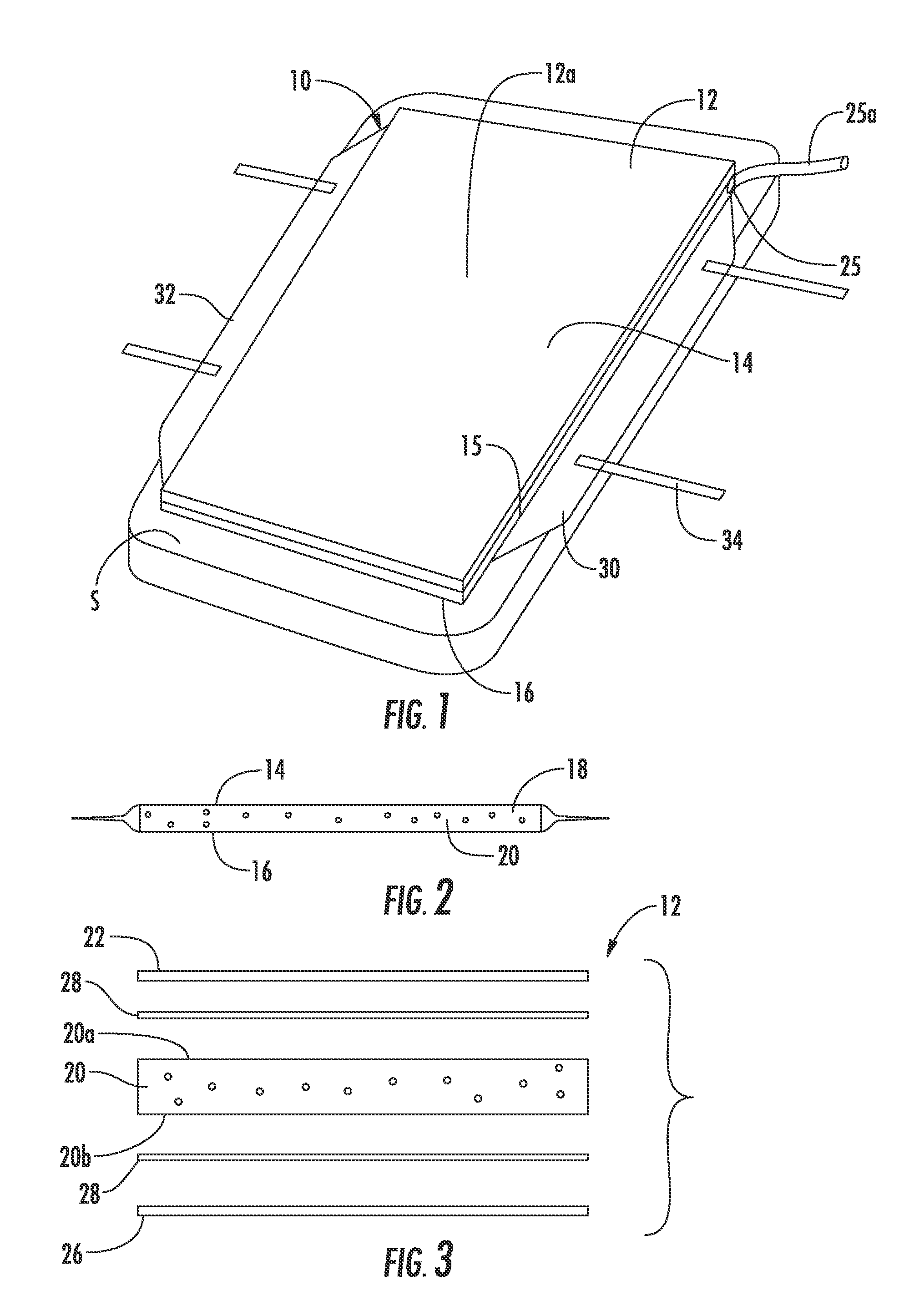
[0056]Referring to FIG. 1, the numeral 10 generally designate a patient transfer device of the present invention. As will be more fully described below, the patient transfer device comprises an air mat 12 that generates an air film and, optionally, across a significant portion, if not substantially it's entire portion, of its lower surface for transferring a patient across a surface and between surfaces. Although the term “patient” is used herein, it should be understood that patient should be broadly construed to not only include people awaiting or under medical care, but also to include invalids or other people in need of assistance. Further, the mat may be operated with a lower air flow than conventional air bearing pallets while still achieving the same or better ease of transfer than prior art air bearing pallets. Because lower air flow is needed, device 10 may be operated with a smaller blower than used heretofore with the prior art air bearing pallets or with a pump, which sa...


PUM


Abstract

A patient transfer device includes a mat, with an upper side and a gas permeable lower side. The mat includes a chamber between its upper and lower sides, which is operable to be in fluid communication with an air source such that when air flows into the mat, the air will flow into the chamber and through the gas permeable lower side to form an air film between the mat and a surface on which the mat is supported at its lower side. In addition, the lower side of the mat is substantially planar when the mat is inflated. A system for controlling the inflation of the mat may be used that automatically adjusts for the inflation of the mat during patient transfer.

Description

BACKGROUND AND TECHNICAL FIELD OF THE INVENTION[0001]The present invention pertains to devices for moving patients and, more particularly, to devices that use air to transfer a patient.[0002]Non-ambulatory patients in a patient facility, such as a hospital or a nursing home, present substantial challenges when such patients must be moved from one location to another. A patient may, for example, need to be moved from a hospital bed to a stretcher and then from the stretcher to a treatment location, such as a surgical table in an operating room. Following treatment, the reverse patient handling sequence may occur; i.e.: the patient is moved from the surgical table, which remains in the operating room, to a stretcher which travels to the patient's hospital room, and then from the stretcher back onto the bed in the hospital room.[0003]In some situations it is preferable that a patient be handled in a manner that minimizes handling or jostling of the patient, for example, in the case of ...

Claims


Application Information

Patent Timeline
Patent Type & Authority Applications(United States)
IPC IPC(8): A61G7/10A47C27/08A47C27/14
CPCA61G7/1028A61G7/1026
Inventor SCHREIBER, AUSTINPATMORE, KEVIN
Owner STRYKER CORP
Why Eureka
Try Eureka