System and method for detection of liquid level in a vessel

a technology of automatic identification and liquid level detection, applied in the field of machine vision systems, can solve the problems of inability to determine the type of cap placed on the vessel, inability to provide accurate information, and inability to provide information about sample quality

Active Publication Date: 2011-03-10
NOVANTA CORP
View PDF50 Cites 56 Cited by
  • Summary
  • Abstract
  • Description
  • Claims
  • Application Information

AI Technical Summary

Benefits of technology

[0007]The present invention provides a system and method for identifying the levels of one or more liquids in a vessel using one ore more appropriately positioned light sources and an optical imager for capturing digital images of the illuminated vessel. For example, a line generator may be positioned on one side of the vessel and oriented to project a line of light that intersects each layer of liquid in the vessel. An optical imager is positioned on the opposing side of the vessel from the laser line generator and o...

Problems solved by technology

Current methods for determining liquid levels are relatively ineffective and do not provide accurate information.
For example, capacitive approaches cannot determine the type of cap placed on the vessel, do not provide any information about sample quality, and will not work if the vessel contains a layer of foam.
In addition, capacitive approaches have low reliability with respect to the detection of the location of the level.
Ultrasonic approaches are also unable t...

Method used


Image

  • System and method for detection of liquid level in a vessel
  • System and method for detection of liquid level in a vessel
  • System and method for detection of liquid level in a vessel

Examples


Embodiment Construction

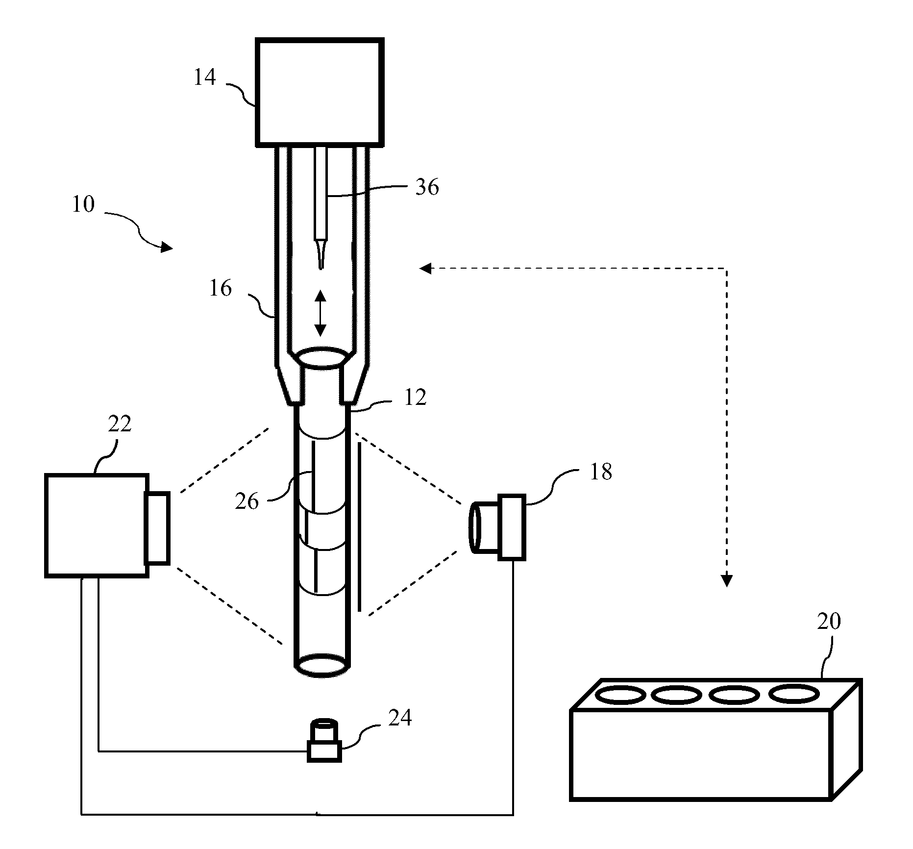
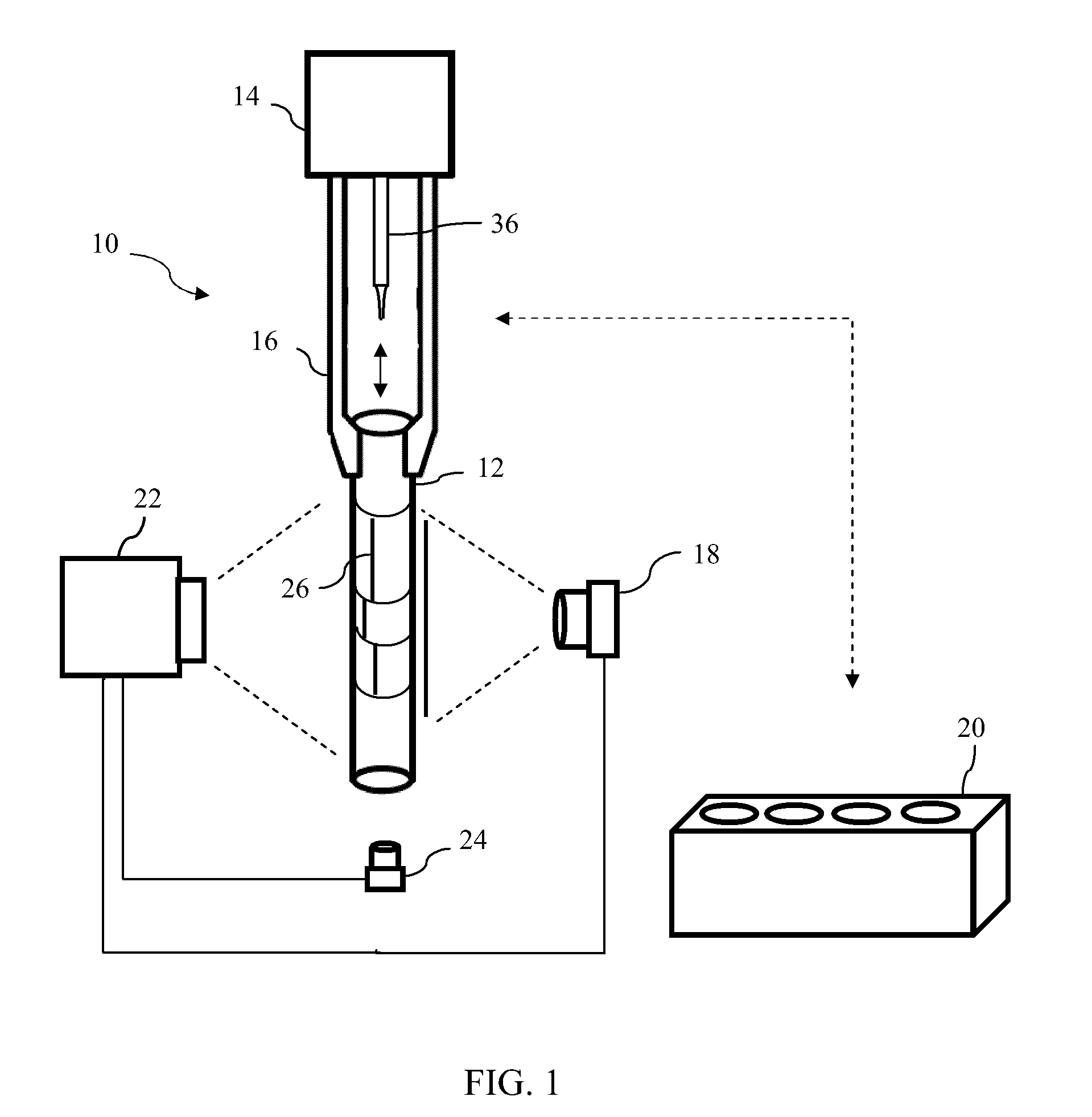
[0014]Referring now to the drawings, wherein like reference numerals refer to like parts throughout, there is seen in FIG. 1 a machine vision system 10 for determining the level of liquids in a vessel, such as a test tube 12, in connection with a robotic handling system 14 or the like. In general, robotic handling systems are motorized systems having an arm 16 for moving and / or transferring patient sample test tubes 12 between designated locations, such as from a rack 20 to another location or back to rack 20. Patient sample tubes can comprise any variety of test tube or comparable vessel and frequently contain one or more different body fluids, such as blood, urine, etc., treatment and processing fluids, that separate into multiple layers.

[0015]As further seen in FIG. 1, system 10 includes a line generator 18, such as a laser line generator, positioned oppositely from an optical imager 22 and oriented to project its line of light toward imager 22. When the spot from a laser is scan...


PUM


Abstract

A system and method for identifying the levels of one or more liquids in a vessel using an optical imager and one or more appropriately positioned light sources and an optical imager for capturing digital images of the illuminated vessel. A laser line generator is positioned oppositely from the imager and oriented to project a laser line through the vessel so that it may be imaged by the imager. A second light source, such as an LED, may be positioned above or below the vessel and oriented to project light downwardly or upwardly through the vessel and its contents. Captured images of the vessel are then processed by a programmable device, such as a microcontroller, to determine the levels of materials in the vessel based on the optical characteristics revealed in the captured image.

Description

BACKGROUND OF THE INVENTION[0001]1. Field of the Invention[0002]The present invention relates to machine vision systems and, more specifically, to a system and method for automatically identifying the level of liquids in a vessel.[0003]2. Description of the Related Art[0004]Machine vision plays an important role in automated and robotic systems, such as assembly line manufacturing, quality control inspection, and sample processing. Conventional systems are generally comprised of an optical imager, such as a charged coupled device (CCD) or similar device using digital imaging technology, which is positioned to capture images of objects that pass in front of the imager. In low-light or enclosed applications, machine vision systems may include an illumination source, such as a bank of light emitting diodes (LEDs), positioned proximately to the imager. The images are subsequently processed to decode information contained in the resulting two-dimensional image, such as 1D linear codes, 2...

Claims


Application Information

Patent Timeline
IPC IPC(8): G01F23/00
CPCG01F23/292
Inventor BRYANT, STEVEN THOMASBARBER, CHARLES PAUL
Owner NOVANTA CORP
Why Eureka
Try Eureka