Vent pipe for an aircraft fuel system vent tank

a technology for aircraft fuel system and vent pipe, which is applied in the direction of rigid containers, transportation and packaging, transportation items, etc., can solve the problems of limited and valuable fuel storage space in aircraft, relative high pressure during filling, and physical damage to the fuel tank system

Inactive Publication Date: 2011-03-10
AIRBUS OPERATIONS LTD
View PDF9 Cites 11 Cited by
  • Summary
  • Abstract
  • Description
  • Claims
  • Application Information

AI Technical Summary

Problems solved by technology

One problem with such surges of liquid fuel is that they may be at a relatively high pressure during filling.
If such pressure is not properly vented then the fuel tank system may be physically damaged.
This is a particular problem if the fuel tank system comprises an integral part of the aircraft structure.
Another problem exists in that fuel storage space in an aircraft is limited and valuable.

Method used


Image

  • Vent pipe for an aircraft fuel system vent tank
  • Vent pipe for an aircraft fuel system vent tank
  • Vent pipe for an aircraft fuel system vent tank

Examples


Embodiment Construction

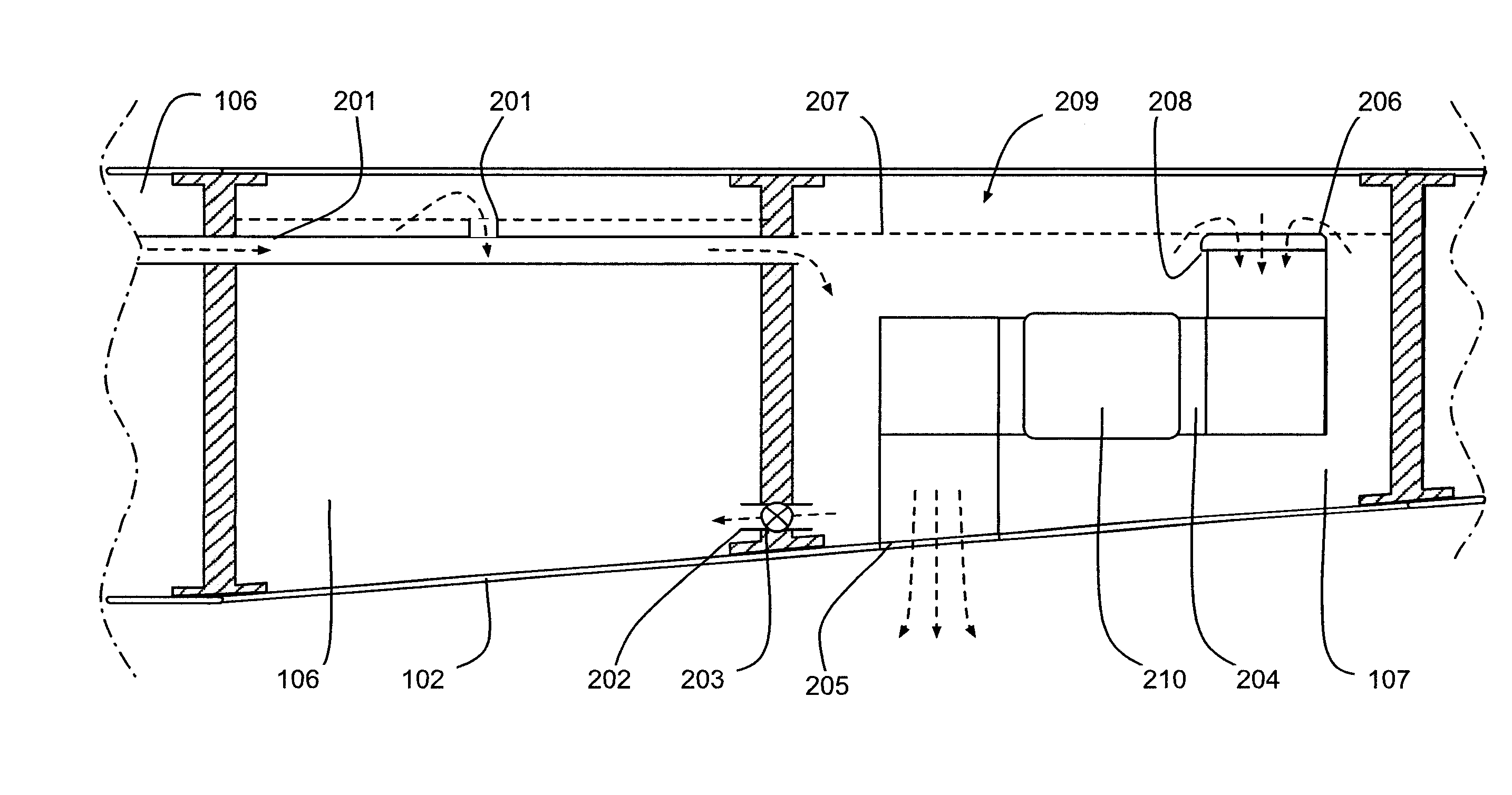
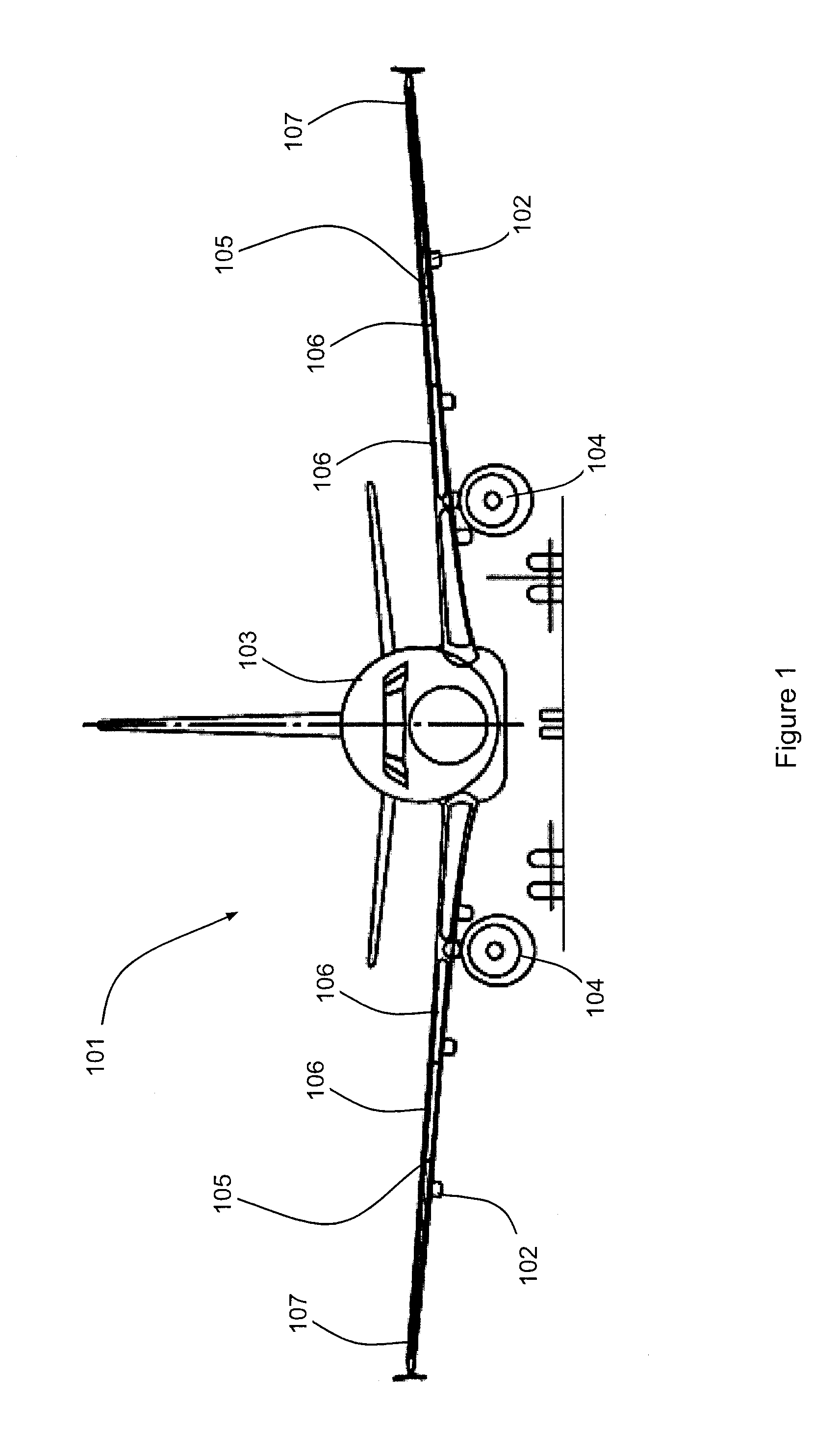
[0012]With reference to FIG. 1, an aircraft 101 comprises a pair of wings 102 faired into a fuselage 103. Each wing 102 carries an engine 104 and part of an internally located fuel tank system 105. The fuel tank system 105 provides fuel to the engines 104. The fuel tank system 105 comprises a set of fuel tanks 106 and two vent tanks 107 each built-in to a respective one of the wings 102. The vent tanks 107 are each located towards the tip of their respective wings 102.

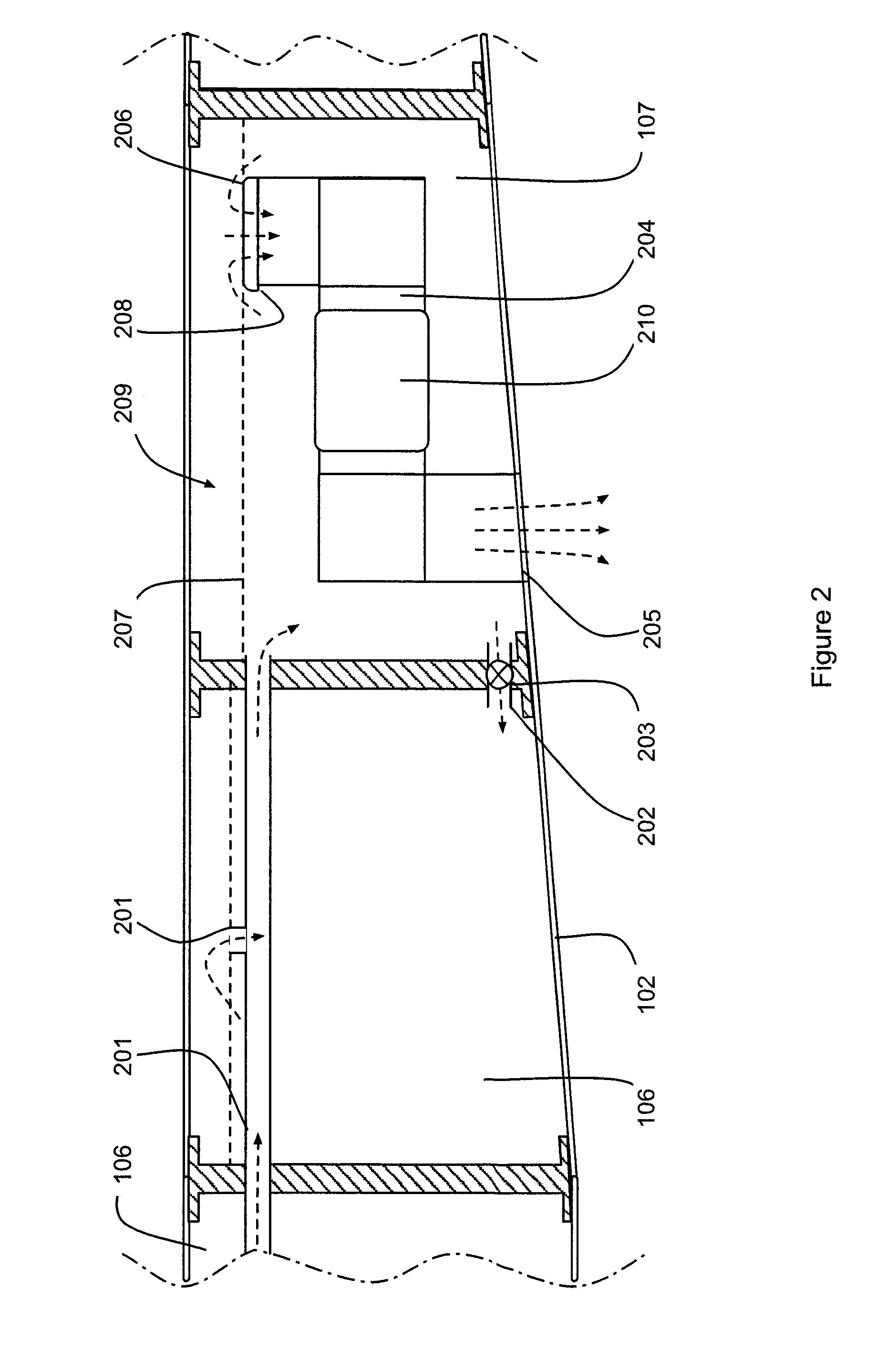
[0013]The vent tanks 107 are arranged to perform a number of functions. Firstly, the vent tanks 107 vent the ullage of each of the fuel tanks 106 to atmosphere to enable the ingress of air required to equalise negative pressure in the fuel tanks as a result of for example, fuel being burned by the engines 104, fuel jettison, de-fuel or a decrease in altitude of the aircraft 101. Secondly, the vent tanks 107 vent the ullage of each of the fuel tanks 106 to atmosphere to enable the egress of positive pressure of air, fue...


PUM


Abstract

A vent pipe is disclosed for use in the vent tank of an aircraft fuel system. The vent pipe is arranged with guide vanes or corner cascades for assisting the flow of fluid around the corners.

Description

FIELD OF INVENTION[0001]The present invention relates to a vent pipe for an aircraft fuel system vent tank.BACKGROUND OF THE INVENTION[0002]Fuel tank systems for aircraft commonly comprise one or more fuel tanks and a vent tank. The vent tank may also be referred to as a surge tank. The vent tank is arranged to provide venting means to vent the fuel tanks to atmosphere. Vent tanks are arranged to allow air to flow from atmosphere into the fuel tanks as they are drained and to allow air, fuel vapour or inerting gasses or a mixture of these to flow out of the tanks to atmosphere as the tanks are filled. In addition, during such fill or drain operations, vent tanks are also commonly required to equalize pressures in normal operation due to ambient pressure changes.[0003]Vent tanks are commonly arranged with a predetermined liquid fuel storage capacity. This capacity provides storage for liquid fuel forced from the fuel tanks and vent system into the vent tank, for example, as a result ...

Claims


Application Information

Patent Timeline
Patent Type & Authority Applications(United States)
IPC IPC(8): B65D90/22
CPCB64C3/34B64D37/32B64D37/005
Inventor LYNAS, CHRISTOPHERJAMES, PETER WILLIAMMELVILLE, ROBERT A.
Owner AIRBUS OPERATIONS LTD
Why Eureka
Try Eureka