Plastic Preform and Single Container for Making a Dual-Container Dispenser

a dual-container and dispenser technology, applied in the direction of single-unit apparatus, transportation and packaging, other domestic objects, etc., can solve the problems of sealing properties and frequent leakage of dual-container dispensers, and achieve the effects of convenient and advantageous manufacturing, easy and advantageous assembly, and low weigh

Active Publication Date: 2011-03-10
PLASTIPAK BAWT S A R L
View PDF8 Cites 2 Cited by
  • Summary
  • Abstract
  • Description
  • Claims
  • Application Information

AI Technical Summary

Benefits of technology

[0006]Such a preform can be easily and advantageously manufactured by injection moulding, and then can be biaxially stretched in a mould, in particular stretch-blow moulded, for forming a single container. In particular, the lower wall of the neck finish can be used for centring and supporting the preform in a mould during the stretch-blow moulding operation. This single container can be easily and precisely assembled with another container of the same type for forming a dual-container assembly.
[0007]In addition, the housing formed by the side wall, up...

Problems solved by technology

The use of extrusion blow-moulding containers enable to achieve only poor sealing properties between the hand-actuated ...

Method used


Image

  • Plastic Preform and Single Container for Making a Dual-Container Dispenser
  • Plastic Preform and Single Container for Making a Dual-Container Dispenser
  • Plastic Preform and Single Container for Making a Dual-Container Dispenser

Examples


Embodiment Construction

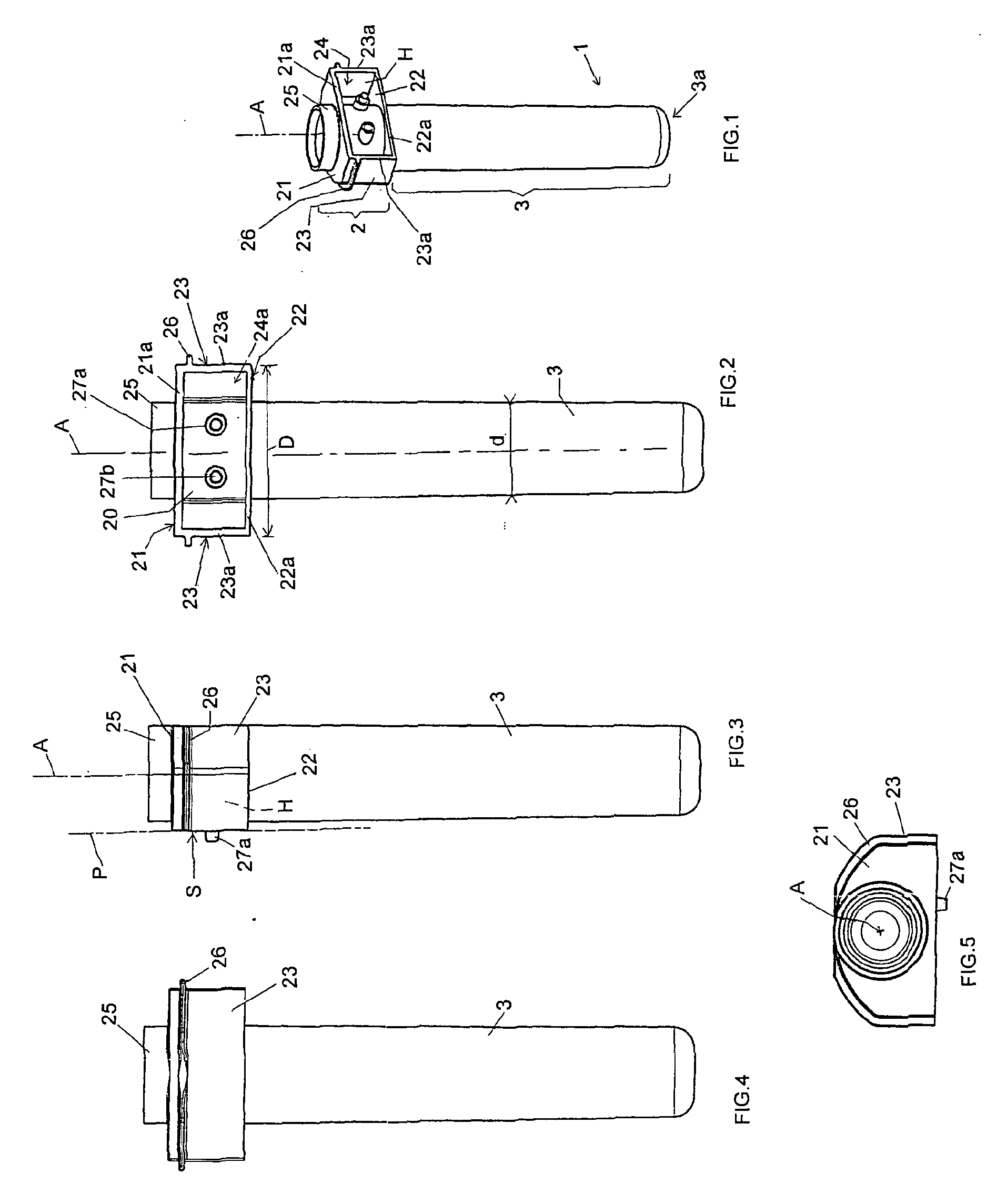
[0036]FIG. 1 shows a thermoplastic preform 1 of the invention a neck finish 2 and a stretchable tubular body 3 closed at its bottom end 3a. The longitudinal axis of the preform 1 is referenced “A” on the drawings.

[0037]Directional words such as “upper”“lower”, “bottom”, “above”, “underneath”, “horizontal”, “vertical” are employed therein by way of description and not limitation with respect to the vertical and upright orientation of the preform or container illustrated in the appended figures.

[0038]This preform 1 is manufactured by the well-known technique of injection moulding. Within the scope of the invention, this preform 1 can be a monolayer preform or a multilayer preform. This preform 1 can be made of any known thermoplastic polymer that can be processed by injection moulding in order to form a preform. Polyester polymers, and in particular homo or copolymer of PET, and polyolefin polymers are the most commonly used, but the invention is however not limited to these particula...


PUM


Abstract

The rigid plastic container (V) is designed for being assembled with another rigid plastic container (V) and forming a dual-container dispenser. The container (V) comprises a neck finish (2) and a stretched body (3′) closed at its bottom end. The neck finish (2) comprises a tubular part (20), an upper wall (21), a lower wall (22) and a side wall (23). The side wall (23) extends between the upper (21) and lower (22) walls and said side wall (23), upper wall (21) and lower wall (22) form a housing (H) for the tubular part (20). The housing (H) comprises an assembly surface (S) formed by the edges of the side wall (23), upper wall (21 and lower wall (22). The tubular part (20) is opened at both ends and forms a path through the upper wall (21), within the housing (H) and through the lower wall (22), for filling the stretched body (31).

Description

TECHNICAL FIELD[0001]The present invention relates to a novel plastic dual-container dispenser, and more especially to a novel plastic dual-container sprayer.PRIOR ART[0002]Plastic dual-container dispensers, and more especially dual-container sprayers, are commonly used for simultaneously dispensing two product, in particular liquids that are separately stored in each single container. In particular, such dual-container sprayers comprise a hand-actuated trigger sprayer that is fastened onto a dual-container assembly. This hand-actuated trigger sprayer generally comprises hand-actuated pumping means. This hand-actuated trigger sprayer can comprise two separate spraying nozzles, each nozzle being supplied with the liquid from one container. In another variant, this hand-actuated trigger sprayer can comprise only one spraying nozzle, the liquids in the two containers being mixed prior spraying. Generally, the two containers are made separately by extrusion blow moulding and are then as...

Claims


Application Information

Patent Timeline
IPC IPC(8): B05B9/03B65D1/02B65D23/00B32B1/08
CPCB05B11/3081B29B2911/1442B29B2911/14033B29B2911/14113B29K2105/258B29B2911/1414B29B2911/14053B29B2911/14026B29B2911/14433B29B2911/14133B29B2911/1404B29C49/16B29B2911/14106B29B2911/1444B65D1/023Y10T428/1352B29K2067/00B29L2031/7158B29B11/08B05B11/3011B29B2911/1408B29B2911/14066B29B2911/14093B65D81/3288B05B11/0078B29K2667/00B29B11/14B29B2911/1402B29C2949/3016B29C2949/302B29C2949/3008B29C2949/26B29C2949/28B29C2949/3012B29C2949/24B29C2949/22B29C2949/3024B29C2949/3026B29C2949/3032B29C2949/3034B29C2949/0772B29C2949/077B29C2949/0773B29C49/071B29C2949/0715B05B11/1011B05B11/1081
Inventor DESSAINT, ALAINDE BACKER, STEFAAN
Owner PLASTIPAK BAWT S A R L
Why Eureka
Try Eureka