Printed antenna

a printed antenna and antenna technology, applied in the field of printed antennas, can solve the problems of miniature demands and design of printed antennas to meet good performance and performan

Inactive Publication Date: 2011-03-10
HON HAI PRECISION IND CO LTD
View PDF3 Cites 3 Cited by
  • Summary
  • Abstract
  • Description
  • Claims
  • Application Information

AI Technical Summary

Problems solved by technology

Therefore, design of a printed antenna to meet good performance and

Method used


Image

  • Printed antenna
  • Printed antenna
  • Printed antenna

Examples


Embodiment Construction

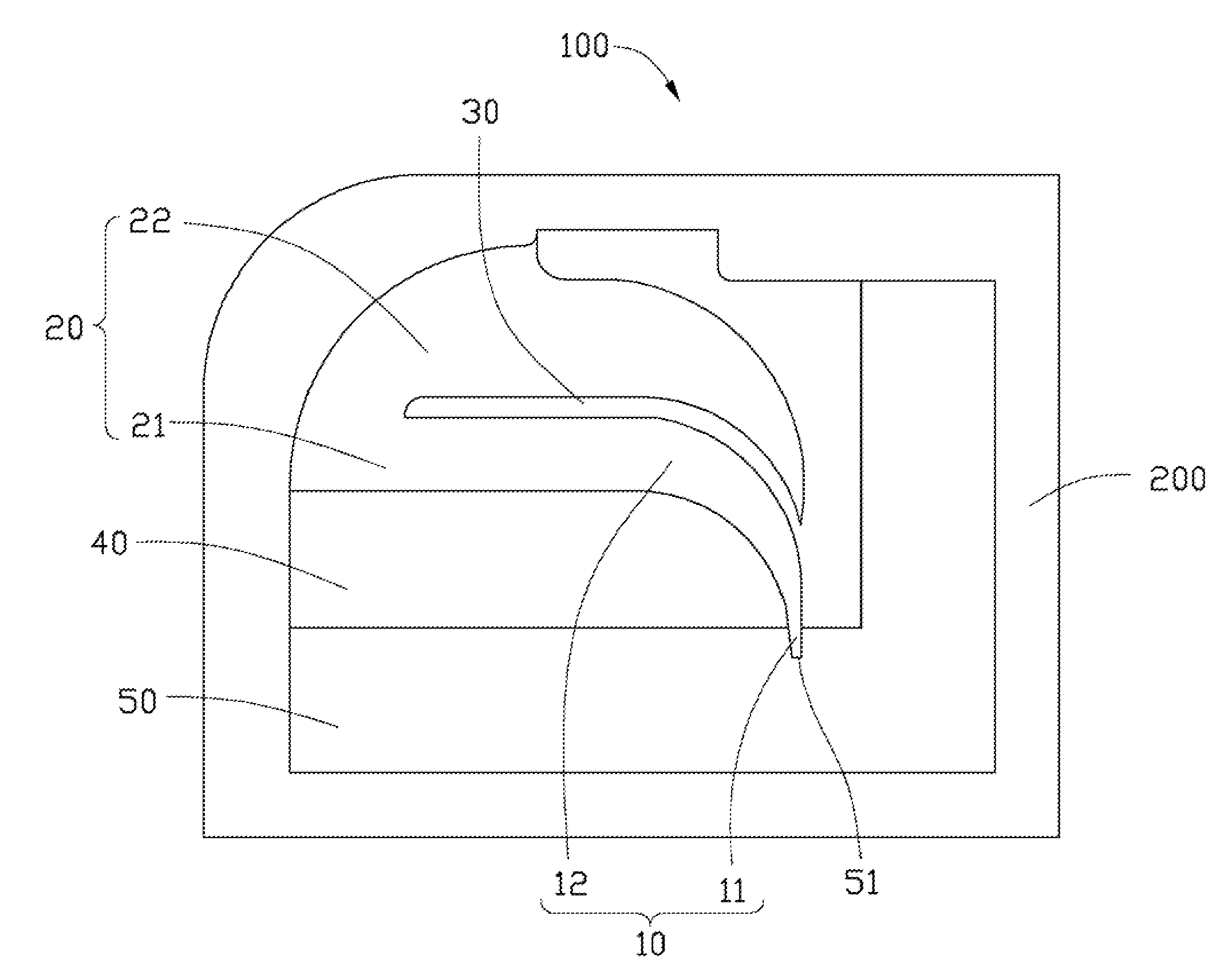
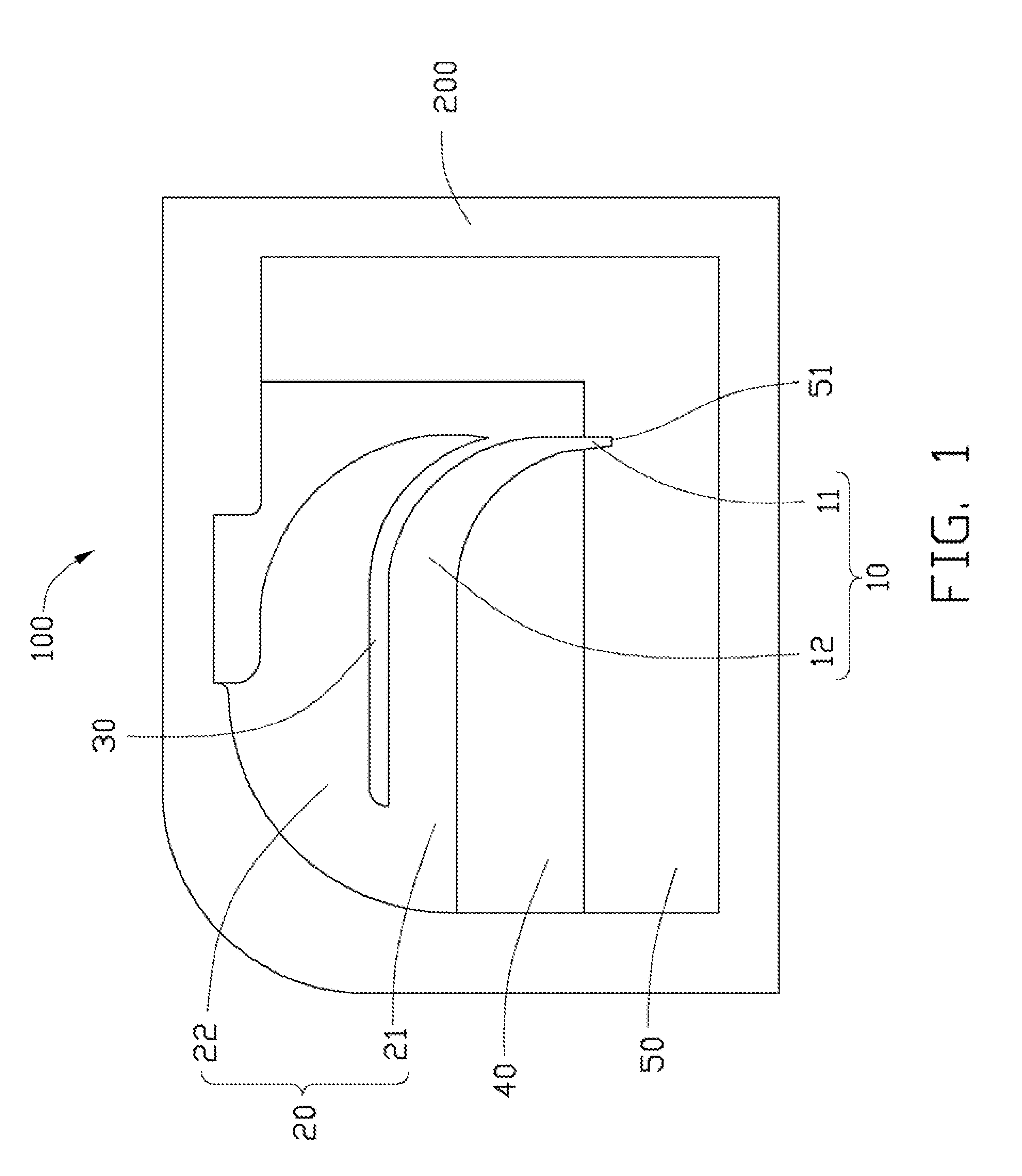
[0010]Referring to FIG. 1, a schematic diagram of one embodiment of a printed antenna 100 according to the present disclosure is shown. The printed antenna 100 comprises a feed portion 10, a radiating portion 20, a clearance zone 40, and a ground portion 50.

[0011]The ground portion 50 is “L” shape surrounding the radiating portion 20. In one embodiment, the ground portion 50 positions the printed antenna 100 to a corner of a substrate 200, to save space for a substrate 200. The ground portion 50 defines a feed via 51.

[0012]The feed portion 10 is shaped as a bent taper, to feed electromagnetic signals. In one embodiment, the feed portion 10 comprises a feed end 11 and a connection end 12. A width of the feed portion 10 is gradually increased from the feed end 11 to the connection end 12. The feed end 11 passes through the feed via 51, and the connection end 12 is connected to the radiating portion 20. In one embodiment, the connection end 12 is substantially vertical to the feed end ...


PUM


Abstract

A printed antenna includes a feed portion and a radiating portion. The feed portion feeds electromagnetic signals, and includes a feed end and a connection end. A width of the feed portion is gradually increased from the feed end to the connection end. The radiating portion includes a first radiator and a second radiator. The first radiator is elongated, and connects to the connection end of the feed portion. One end of the second radiator is connected to the first radiator, and the other end is free. The free end is bend and bent along the feeding portion, and defines a slot between the second radiator and the first radiator and the feeding portion.

Description

BACKGROUND[0001]1. Technical Field[0002]Embodiments of the present disclosure relate to antennas, and especially to a printed antenna.[0003]2. Description of Related Art[0004]Inner printed antennas are traditionally designed as a monopole antenna 1, as shown in FIG. 5, and need a large area to be a ground area 3 and a clearance zone 2. Therefore, design of a printed antenna to meet good performance and miniature demands has proven a significant challenge in the industry.BRIEF DESCRIPTION OF THE DRAWINGS[0005]FIG. 1 is a schematic diagram of one embodiment of a printed antenna according to the present disclosure;[0006]FIG. 2 is a graph showing one exemplary embodiment of a return loss of the printed antenna of FIG. 1;[0007]FIG. 3 is a horizontal radiation pattern of the printed antenna of FIG. 1;[0008]FIG. 4 is a perpendicular radiation pattern of the printed antenna of FIG. 1; and[0009]FIG. 5 is a schematic diagram of another embodiment of a printed antenna according to the present ...

Claims


Application Information

Patent Timeline
IPC IPC(8): H01Q13/10H01Q1/36
CPCH01Q1/36H01Q9/0407H01Q1/48
Inventor CHEN, LUNG-PAO
Owner HON HAI PRECISION IND CO LTD
Why Eureka
Try Eureka