Double-fiber reflection type collimator and industrial equipment

A reflective and collimator technology, which is applied in the direction of instruments, light guides, optics, etc., can solve the problems of easy burning of the end face of the optical fiber, and achieve the effects of reducing power density, solving easy burning, and increasing the area

Pending Publication Date: 2020-09-18
珠海光艺科技有限公司
View PDF0 Cites 0 Cited by
  • Summary
  • Abstract
  • Description
  • Claims
  • Application Information

AI Technical Summary

Problems solved by technology

[0004] The first purpose of the present invention is to provide a high-efficiency and stable dual-fiber reflective collimator that solves the problem that the end face of the fiber is easily burned in high-power or short-wavelength applications

Method used


Image

  • Double-fiber reflection type collimator and industrial equipment
  • Double-fiber reflection type collimator and industrial equipment
  • Double-fiber reflection type collimator and industrial equipment

Examples


no. 1 example

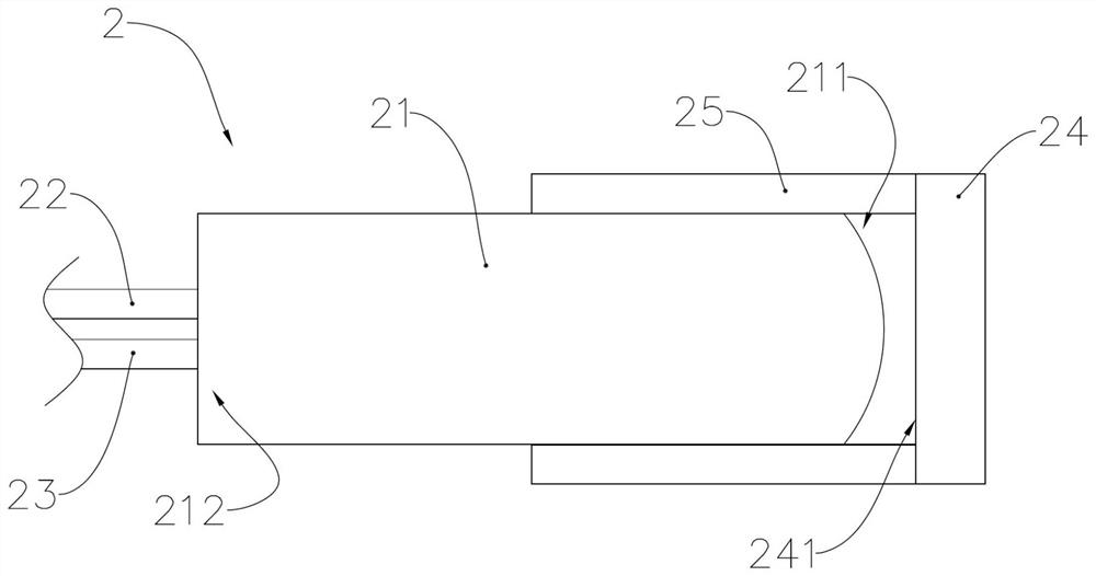
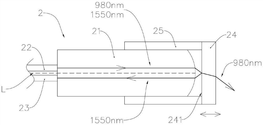
[0026] refer to figure 2 with image 3 , the dual-fiber reflective collimator includes a lens 21, a first optical fiber 22, a second optical fiber 23, a filter 24 and a sleeve 25. The lens 21 (C-LENS) can be arranged as a cylinder made of quartz, and there is no internal 8-degree slope, the inside of the lens 21 is complete, the lens 21 is provided with a first end surface 211 and a second end surface 212 at both ends of the optical path direction, the first end surface 211 is arranged in a convex spherical arc shape, and the second end surface 212 is arranged in a plane , the first optical fiber 22 and the second optical fiber 23 are welded to the second end face 212 respectively, and the first optical fiber 22 and the second optical fiber 23 are arranged symmetrically with respect to the optical axis L of the lens 21 .

[0027] The casing 25 is made of quartz or glass, and is arranged in a hollow tubular shape. The lens 21 is arranged in the casing 25, and the filter 24 is...

no. 2 example

[0031] refer to Figure 5 , the dual-fiber reflective collimator includes a self-focusing lens 31, a first optical fiber 32, a second optical fiber 33, and a filter 34. The self-focusing lens 31 (G-LENS) can be arranged in a cylinder made of quartz, and the self-focusing lens The inside of 31 is complete, lens 31 is respectively provided with first end face 311 and second end face 312 at the two ends of optical path direction, the end faces of two planes are all perpendicular to the optical axis of self-focusing lens 31, and first optical fiber 32 and second The optical fibers 33 are respectively fused with the second end face 312, and a first capillary 321 is provided outside the core of the first optical fiber 32, a second capillary 331 is provided outside the core of the second optical fiber 33, the first capillary 321 and the second capillary 331 They are welded to the second end face 312 respectively, and the first optical fiber 22 and the second optical fiber 23 are arra...


PUM


Abstract

The invention provides a double-fiber reflection type collimator and industrial equipment. The device comprises a lens, a first fiber, a second fiber and a filter. A first end surface and a second endsurface are respectively arranged at two ends of the lens in the light path direction; the first end surface is arranged in a convex spherical arc shape; the first optical fiber and the second optical fiber are respectively welded with the second end surface; the first optical fiber and the second optical fiber are symmetrically arranged about the optical axis of the lens; the filter is plated with a transflective film on the end surface opposite to the first end surface; and the characteristics of the transflective film comprise light transmission of a first wavelength and light reflection of a second wavelength. The lens is directly welded through the optical fiber; the area of an interface where light is incident to air is increased, the power density is reduced, and the problem that the end surface of the optical fiber is prone to being burnt down in high power is solved; and the filter is easier to assemble and more stable due to the fact that no 8-degree air gap exists between the optical fiber and the lens and incident and reflected light paths are symmetrical.

Description

technical field [0001] The invention relates to the field of optical equipment, in particular to a dual-fiber reflective collimator and industrial equipment. Background technique [0002] The collimator is an optical component used for input and output of fiber optic devices. The divergent light device emitted by the fiber becomes parallel light through the front convex lens. Its function is to couple the light into the required device with maximum efficiency. Medium or easy acceptance of optical signals for maximum efficiency. refer to figure 1 , figure 1 It is the optical path structure diagram of the existing dual-fiber reflective collimator. The dual-fiber reflective collimator includes a C-lens lens 11, an optical device 12, and a C-lens lens 13 arranged along the optical path. There is an 8-degree slope, and the C-lens lens 11 is arranged in a double pigtail arrangement. [0003] In some applications, the optical power reaches 10 watts or even higher, and the power...

Claims


Application Information

Patent Timeline
Patent Type & Authority Applications(China)
IPC IPC(8): G02B6/32G02B6/255G02B6/293
CPCG02B6/2551G02B6/293G02B6/32
Inventor 傅谦
Owner 珠海光艺科技有限公司
Why Eureka
Try Eureka