
Particle detection

a particle detection and particle technology, applied in the field of particle detection systems, can solve the problems of preventing the system from detecting smoke, and setting up and maintaining such a system, so as to reduce the effect of multi-path effects

Active Publication Date: 2011-03-10
GARRETT THERMAL SYST LTD
View PDF60 Cites 113 Cited by
  • Summary
  • Abstract
  • Description
  • Claims
  • Application Information

AI Technical Summary

Benefits of technology

[0079]In a further aspect there is provided a method in an AVSD system including: modulating the intensity of emission of a light source: and modulating the sensitivity of a corresponding sensor such that the sensitivity of the sensitivity of the light sensor is reduced from a peak value at the time or arrival of a peak in intensity of the emitted light.
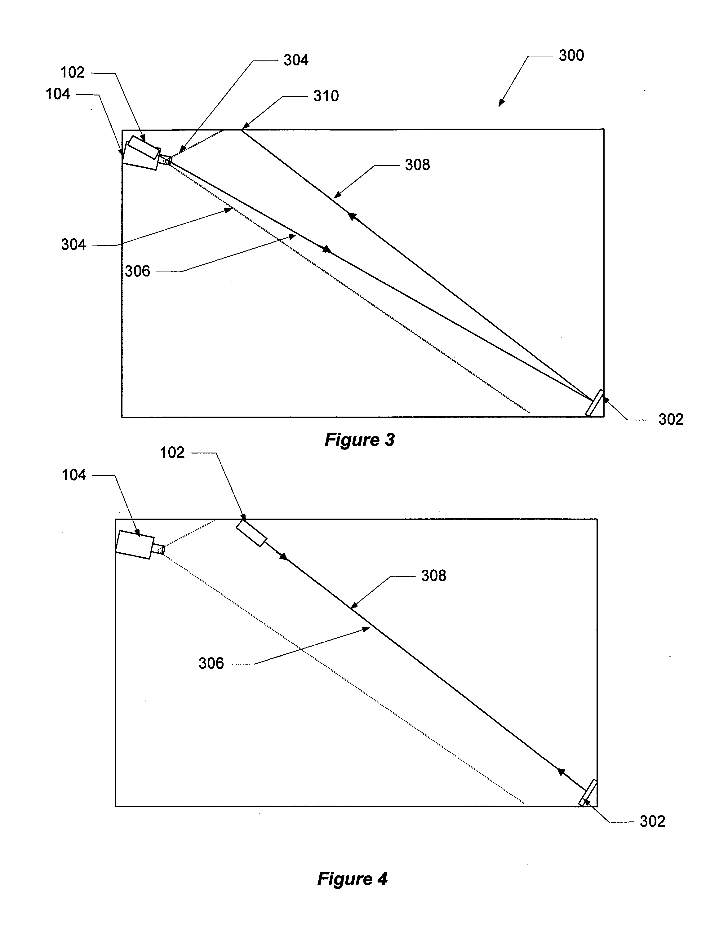
[0084]The method can include reducing the beam power in the event an intrusion has been detected. The method can include reflecting the beam across the volume being monitored.
[0113]In another aspect the present invention provides a method in a particle detection system configured to detect particle in an air volume, the system including: a primary illumination means for directing a beam of radiation across the air volume being monitored, an image sensor is positioned to capture images of a least part of the beam; means to analyse the captured images to detect the presence of particles within the volume on the basis of scattered radiation captured in the images; and at least one secondary illumination means which emits light at least partly in the visible part of the electromagnetic spectrum, the method including: detecting an ambient light level: setting the light intensity of the secondary light source on the basis of the ambient light level so as to minimise the level of visibility of the light from the secondary light source, but maintain detectability of light from the secondary light source by a light sensor of the system.
[0156]In another aspect the present invention provides a method of processing a light scattering signal from particle detection system: receiving a light scattering signal; identifying a temporary peak in received scattered light intensity in the signal; and smoothing the temporary increase in received scattered light intensity of the signal.
[0177]In another aspect the present invention provides a fractional light loss measurement device configured to measure fractional light loss of a beam of light, said beam defining a cross section at the measurement device, fractional light loss measurement device including a light sensitive element configured to measure light from an area greater than the cross section of the beam. The light sensitive element can have a light receiving surface larger than the cross section of the beam. The device can include an optical arrangement able to receive light from an area greater than the cross section of the beam and direct it onto the light sensitive element. The fractional light loss measurement device can include means to prevent laser speckle, e.g. a defocusing lens.
[0180]The system can include one or more of the following, to reduce multi-path effects in the projection of the beam onto the fractional light loss measurement device: jittering the beam position, de-cohering the beam; and using of a non-coherent primary light source.

Problems solved by technology

As noted in those patent publications one problem that may be faced by such system is that of objects other than smoke entering the beam or field of view of the image sensor.
This can have several effects; firstly it can cause a false alarm by imitating the effect of smoke.
Secondly, encroaching objects may prevent the system from detecting smoke by blocking the path of the beam across the volume being monitored or by blocking the view of part of the beam by the image sensor.
Thirdly, it may be unsafe if a person (or animal) passes through the beam.
Another issue to consider is the set-up and maintenance of such a system.

Method used


Image

  • Particle detection
  • Particle detection
  • Particle detection

Examples


third embodiment

[0377]There are other embodiments of such a system that can be created by making various modifications to the present embodiment. For example, the polarisation filter may be fixed and the polarisation direction of the light source may be rotatable in order to project light in the first polarisation direction and a second polarisation direction. In an alternative embodiment the system may be fitted with two cameras with polarising filters each set to monitor the light beam in different polarisation directions. In a third embodiment, double imaging may be employed by using a beam splitter to divide a beam into two to thereby present two identical images to the camera, but one via a parallel polariser and the other via a cross polariser. Alternatively, two of the AVSD systems can be arranged in close proximity each configured to operate in different polarisation orientations.

[0378]Another variation is to use circular or elliptical polarisations. As with linear polarisation, matching th...

first embodiment

[0565]FIG. 33 illustrates schematically the beam steering mechanism used in a preferred form of the present invention. In this case the mechanism operates by changing the direction of a mirror mounted on the mechanism, although other optical components could be mounted thereon. The beam steering mechanism 3300 is advantageously made up from 2 or more stages mounted on top of each other. The first stage 3304 is steerable relative the mounting 3302, and provides coarse control over a large range of movement which is particularly useful for initial coarse alignment of the particle detection system at installation. Preferably the first stage can provide more than 40 degrees travel with an accuracy of, say ±1 degree.

[0566]The second stage 3306, mounted on the first stage 3304 and independently steerable thereon, provides fine control over a narrower range of movement, which is useful for precise alignment during commissioning and for maintaining alignment in the event of drift. It may al...


PUM

PropertyMeasurementUnit
wavelengthsaaaaaaaaaa
angleaaaaaaaaaa

Abstract

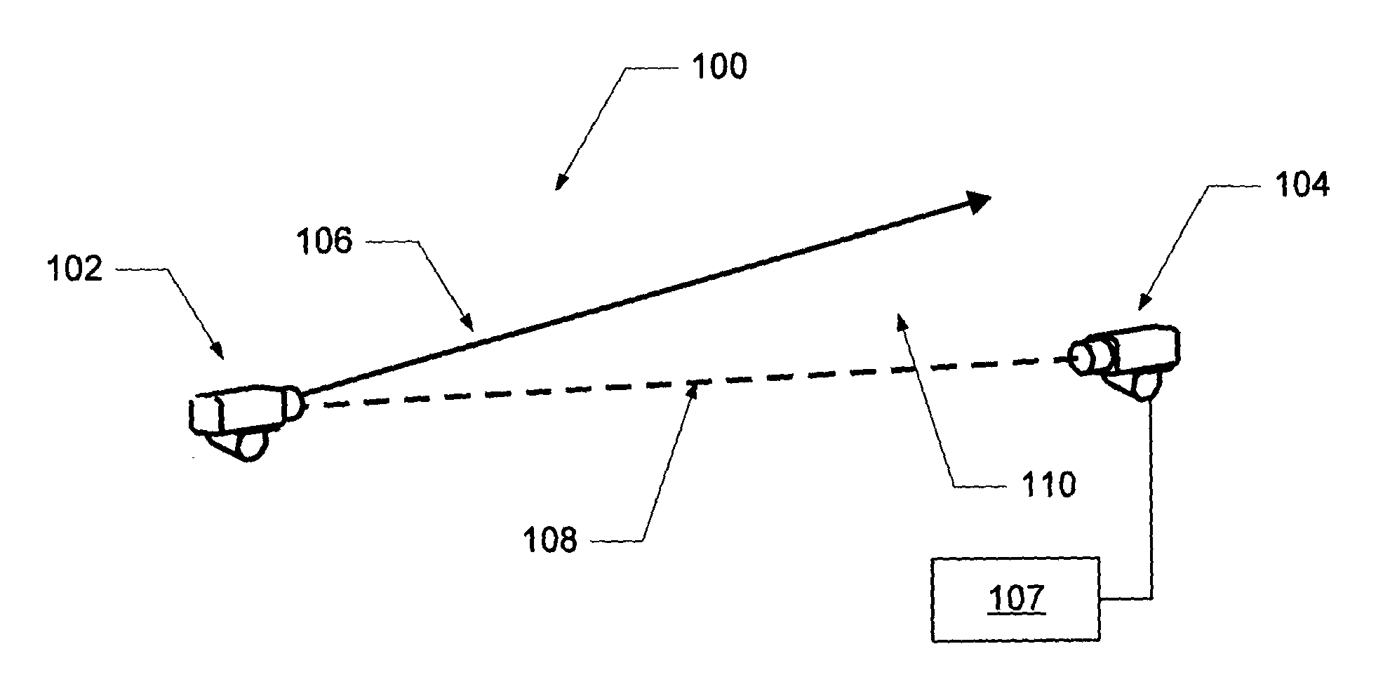
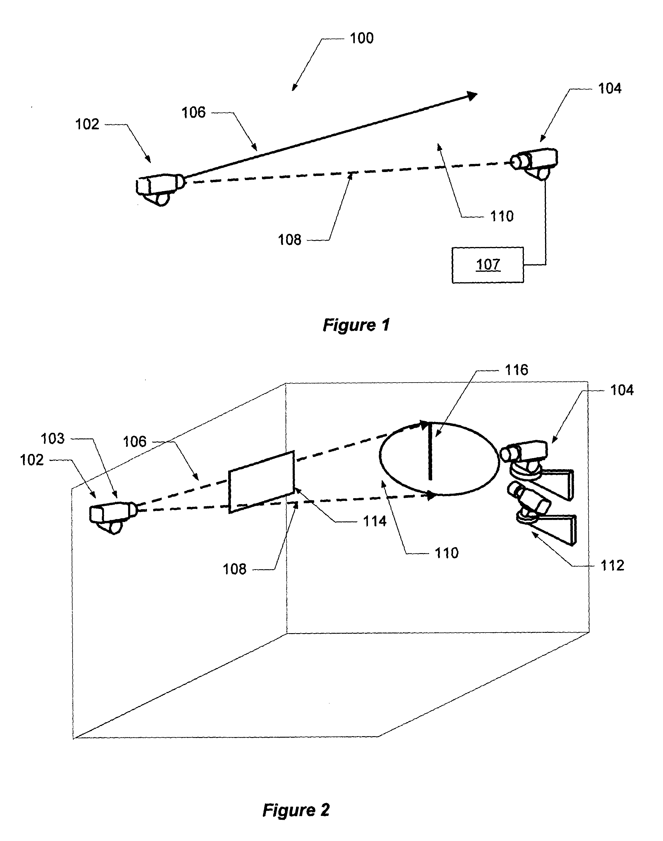
A particle detection system (100), such as an active video smoke detection system, includes at least one illumination means (102) for directing a beam (106) of radiation through at least part of the air volume being monitored (110), an image sensor (104) is positioned to capture images of at least part of a beam (106) from illumination means (102); and means to analyse (107) the captured images to detect the presence of particles within the volume. At least 29 different aspects are described for improving the sensitivity, usability, and robustness of particle detection. These include, for example, configuring illumination means (102) to create a curtain of light or a rapidly-scanned beam across the air volume (110), and configuring a reflector to steer or change direction of a beam reflected from illumination means (102).

Description

FIELD OF THE INVENTION[0001]The present invention relates to systems and methods applicable to particle detection systems. The preferred embodiment of the present invention relates to systems and methods adapted to detect smoke, and more particularly to systems and methods applicable to active video smoke detection. While it is convenient to describe the present invention in this context, the present invention should not be seen as being limited to that exemplary field of application.BACKGROUND OF THE INVENTION[0002]Active video smoke detection (AVSD) is the name that has been coined by Xtralis Pty Ltd for particle detection systems (most preferably smoke detection systems) that use video analysis techniques to detect smoke in an air volume that is actively illuminated, e.g. by a laser or other electromagnetic (EM) radiation source.[0003]Systems and methods for performing AVSD have been described in international patent publications WO 2004 / 102498 and WO 2006 / 001723 in the name of V...

Claims


Application Information

Patent Timeline
Patent Type & Authority Applications(United States)
IPC IPC(8): G01N21/00
CPCG01N15/06G08B17/125G01N2015/0693G01N21/53G08B17/107G08B29/18G08B29/185G01N15/075G01N15/0656G01N21/532H04N5/32H04N7/18
Inventor KNOX, RONAJAY, KEMALBOETTGER, KARL
Owner GARRETT THERMAL SYST LTD
Learn More