Computer, PDA or telephone lens cover

a technology for telephones and computers, applied in the field of camera or projector covers, can solve problems such as the inability of the camera to view objects

Inactive Publication Date: 2011-03-10
WEISS DAVID G
View PDF2 Cites 119 Cited by
  • Summary
  • Abstract
  • Description
  • Claims
  • Application Information

AI Technical Summary

Benefits of technology

[0010]The cover may be made from a wide variety of materials such as metal, plastic, wood, KEVLAR, vinyl, neoprene, paper, cardboard, recycled materials, etc. In various embodiments, the cover may attach via a self-adhesive backing onto the computer or telephone, clip onto a recessed area of the camera, clip onto the computer display, clip over the camera lens, etc. The size of the cover may range from just large enough to cover the camera or projection lens itself, just large enough to cover the recessed area in which the lens sits, or large enough to easily cover the entire recessed area.

Problems solved by technology

When the cover is opaque, the camera cannot view objects when the cover is closed, or may not be able to view them clearly.

Method used


Image

  • Computer, PDA or telephone lens cover
  • Computer, PDA or telephone lens cover
  • Computer, PDA or telephone lens cover

Examples


first embodiment

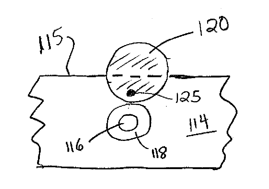
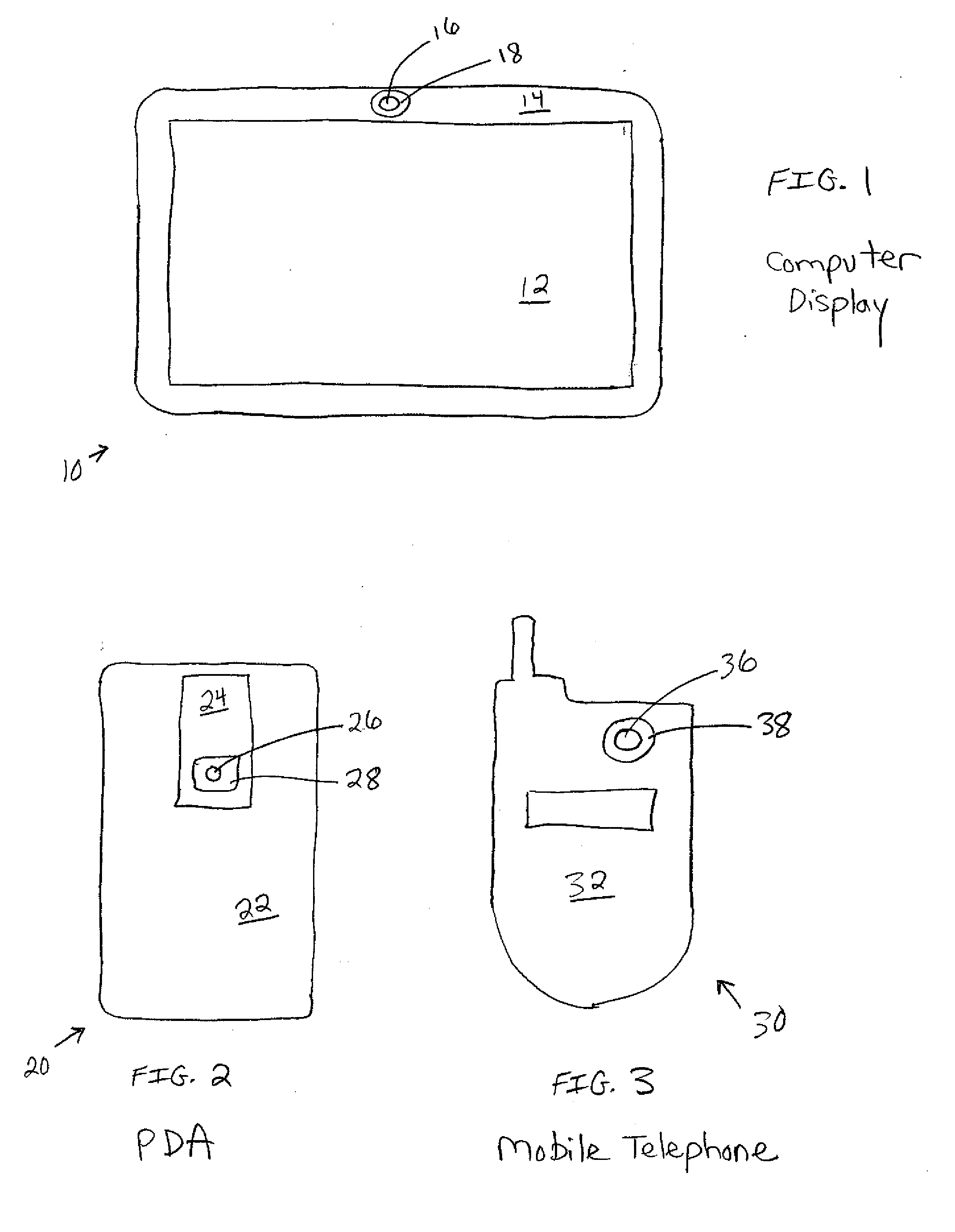
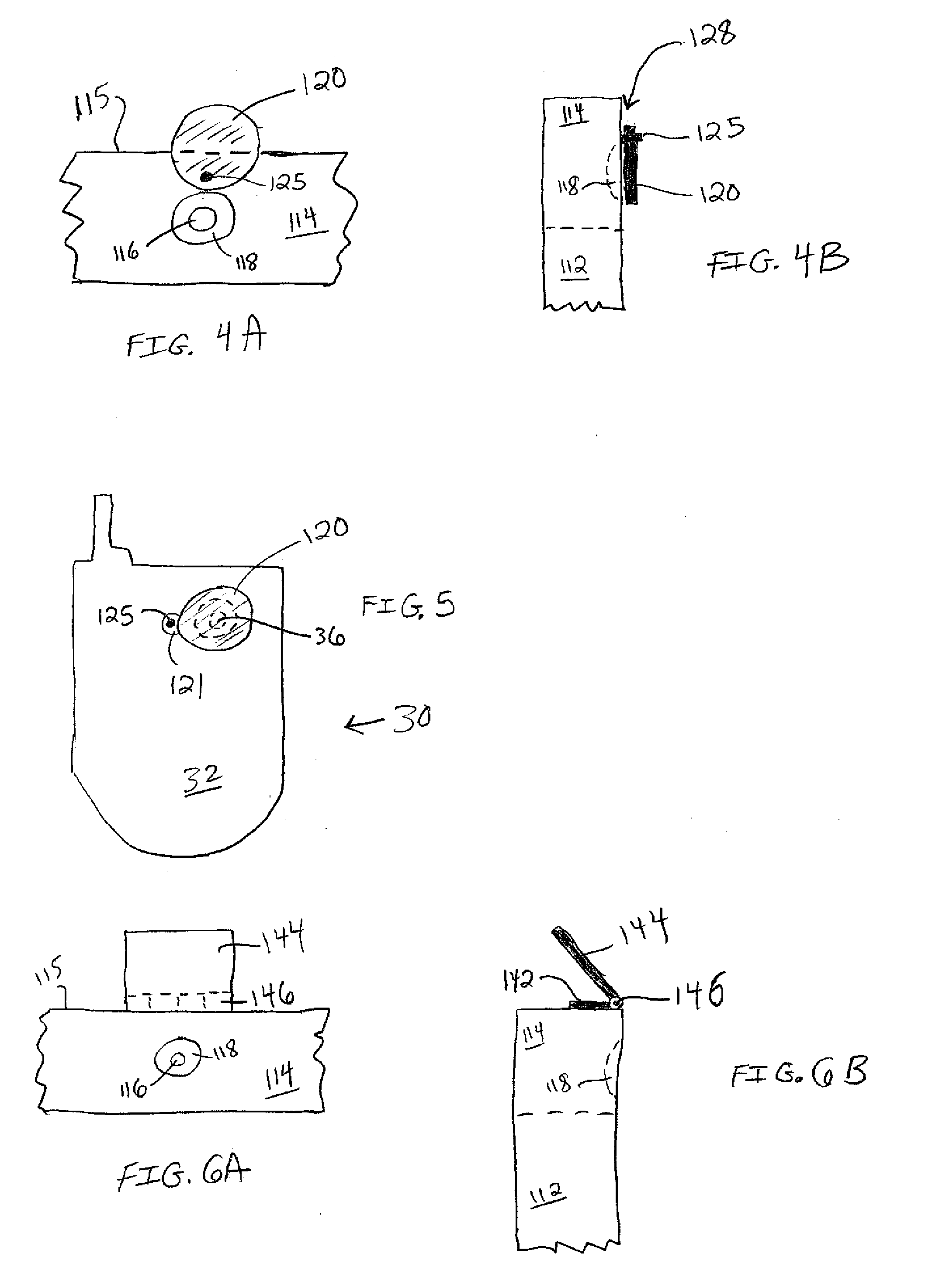
[0032]FIGS. 4A and 4B illustrate the cover of the present invention in which it pivots in order to cover the lens. Shown is a border area 114 in which sits a camera lens 116 within a recessed area 118. Border area 114 may correspond to area 14 which is the top part of the display of a laptop or desktop computer, may correspond to area 24 which is a portion of the back surface of a smartphone, or may correspond to area 32 which is the front surface of a flip telephone. Edge 115 is the top edge of the border area 114 meaning that it may correspond to the top edge of display 10, the top edge of PDA 20, or the top edge of mobile telephone 30.

[0033]As shown, cover 120 includes within its circumference a pivot pin 125 that is affixed to the surface of area 114. The cover is allowed to pivot around this pin such that in the open position (as shown) the lens 116 is allowed to receive (or project) images. By fixing the cover to the surface fairly tightly with the pivot pin, friction keeps th...

second embodiment

[0036]FIG. 5 illustrates a second embodiment in which the cover is mounted upon a mobile telephone 30. In this embodiment cover 120 also pivots around pivot pin 125 in order to cover or uncover lens 36. Formed as part of cover 120 is a protuberance 121 of any suitable shape that closes the pivot pin 125. Thus, the pivot pin is not within the circumference of the cover proper, as it is in FIG. 4A. In this embodiment, friction again may be used to keep the cover either open or closed.

third embodiment

[0037]FIGS. 6A and 6B illustrate a third embodiment in which the cover hinges in order to cover the lens. The cover includes a fixed portion 142 attached to the top of the computer, a hinge portion 146, and a movable portion 144. FIG. 6A shows a front view in which the movable portion 144 has been raised upward and the lens 116 is clear, while FIG. 6B is a side view of the same situation. When desired, the user manually moves portion 144 downward so that it hangs more or less straight down vertically and covers the camera lens. When used with a computer display 10, gravity holds the cover down. When used with PDA 20 or telephone 30, it may be necessary to fix movable portion 144 to surface 114 using hook and loop closures, a snap, a latch, or other techniques described herein. Hinge portion 146 may be a conventional pin-type hinge using rigid materials, or may simply be a crease in flexible materials such as soft plastic. The other embodiments described below in which a hinge is use...


PUM


Abstract

A lens cover covers a camera lens or a projection lens formed in the frame of a computer display or in the body of a personal digital assistant or mobile telephone. The cover is movable to allow the lens to operate, yet allow the cover to remain with the device. One cover pivots around a pivot point to cover or uncover the lens. Another cover hinges in order to cover or uncover the lens. Another cover slides back and forth. Another cover hangs upon a hook located above the lens. Another cover is a suction cup applied over the lens. Another cover slides back and forth hanging on the top edge of the computer display. The cover may be fixed in place using gravity, friction, a snap, hook and loop closures, suction, or a ZIPLOC-type mechanism. The cover or its attaching means may be fixed to the computer or telephone using a self adhesive.

Description

CROSS-REFERENCE TO RELATED APPLICATIONS[0001]This application claims priority of U.S. provisional patent applications No. 61 / 051,056 filed May 7, 2008 and No. 61 / 054,687 filed May 20, 2008, both entitled “Computer Camera and Webcam Cover,” and which are hereby incorporated by reference.FIELD OF THE INVENTION[0002]The present invention relates generally to computing devices and cameras. More specifically, the present invention relates to a cover for a camera or projector typically found on computing devices and mobile telephones.BACKGROUND OF THE INVENTION[0003]Many desktop and laptop computers these days have a small camera lens integrated into the frame of the display or monitor of these computers. The camera lens may then be easily used by the user of the computer to take a picture of himself or herself, or to transmit still or video images while sitting in front of the computer. The ease of use of such a camera lens can also be a drawback, though. A user may not realize that the ...

Claims


Application Information

Patent Timeline
Patent Type & Authority Applications(United States)
IPC IPC(8): G02B23/16
CPCH04M1/0264H04N5/2257H04N5/2251G03B11/041G03B11/043H04N23/50H04N23/57G06F21/83
Inventor WEISS, DAVID G.
Owner WEISS DAVID G
Why Eureka
Try Eureka