


Quick Research
Generate reliable direction feasibility study reports for your R&D in just a few steps.

Technical Q&A
Discover and master advanced knowledge NOW. Basics, ideas, possibilities, all at once.

Find Solutions
As an expert in R&D theories, this can generate solutions to your technical problems instantly.

Evaluate Feasibility
Analyze your overall solution with one click, know your potential R&D risks in advance.

Monitor Landscape
Get weekly tech updates, stay abreast of the latest tech innovations and key insights.
Zoom lens system and imaging apparatus including the same
- Summary
- Abstract
- Description
- Claims
- Application Information
AI Technical Summary
Benefits of technology
Problems solved by technology
Method used
Image

Examples
first embodiment
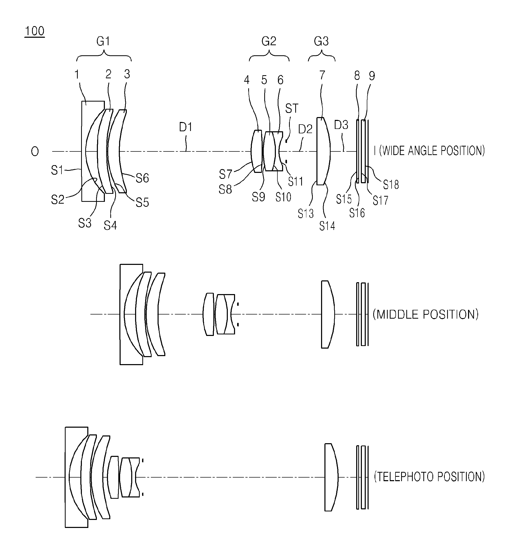
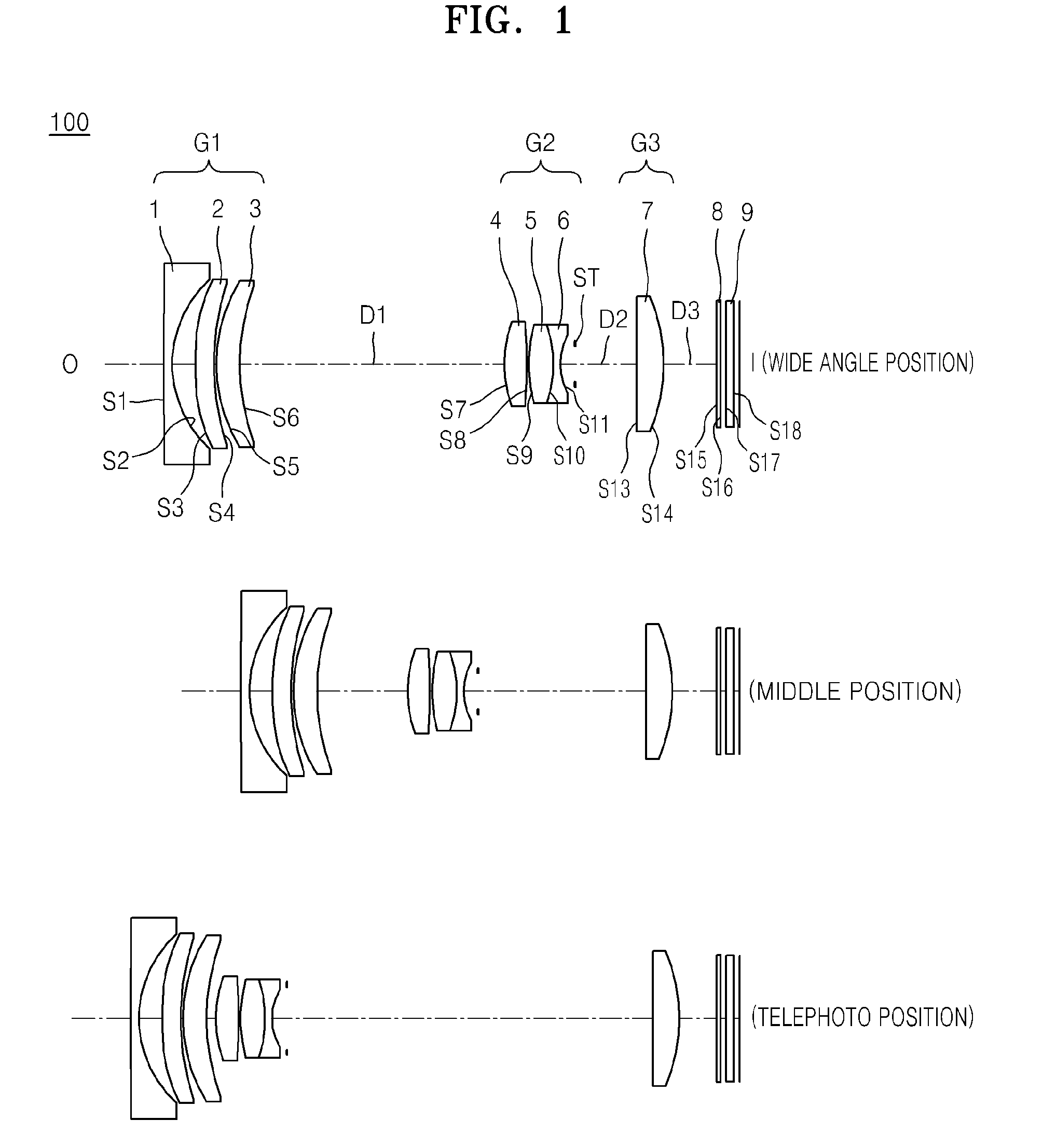
[0052]FIG. 1 illustrates wide angle position, middle position, and telephoto position configurations of a zoom lens system according to the first embodiment. Schematic data of the zoom lens system according to the first embodiment is given below in Table 1.
TABLE 1f: 4.83~10.79~22.95Fno: 3.61~5.74~6.072ω: 77.45~39.51~19.16R (Radius ofLens SurfaceCurvature)Dn (Thickness)NdVdOBJ:INFINITYINFINITYS1:146.3250.5500081.83481042.72S2:7.2191.711200S3:15.184011.0000001.53120056.51ASP:K: 2.336867A: −.541032E−03B: 0.389622E−04C: −.501044E−06D: 0.900976E−08S4:13.899810.100000ASP:K: 1.284154A: −.592427E−03B: 0.377363E−04C: −.548917E−06D: 0.113721E−07S5:9.006021.5102911.94594517.9843S6:12.25809D1S7:6.387081.5286161.68997049.0000ASP:K: −4.383997A: 0.119854E−02B: −.779258E−04C: 0.694829E−06D: −.279409E−06S8:−44.777660.100000ASP:K: 84.649616A: .305905E−03B: .103149E−04C: 0.785226E−06D: −.211495E−06S9:9.593391.5253941.88300040.8054S10:−5.710470.4000001.69895030.0505S11:3.713270.830000ST:INFINITYD2S13:−...
second embodiment
[0055]FIG. 3 is a diagram showing a zoom lens system according to a second embodiment. Schematic data of the zoom lens system according to the second embodiment is given below in Table 3.
TABLE 3f: 5.00~11.05~23.30Fno: 3.55~5.65~5.952ω: 75.55~38.64~18.88R (Radius ofLens SurfaceCurvature)Dn (Thickness)NdVdOBJINFINITYINFINITYS1:900.000000.5500001.82386844.9988S2:7.006671.7388571.5135851.54S3:11.257331.0000001.4583030.5100ASP:K: −0.747677A: −0.801049E−03B: 0.281353E−04C: −0.312632E−06D: 0.151216E−07S4:9.247860.300000ASP:K: 1.314027A: −.135625E−02B: 0.269031E−04C: 0.598477E−06D: 0.124753E−07S5:10.755011.5660911.94594517.9843S6:19.33745D1S7:6.565371.6746451.67520350.4243ASP:K: −4.327212A: 0.122099E−02B: −.658906E−04C: 0.209007E−05D: −.492565E−07S8:−26.802470.100000ASP:K: 53.132776A: 0.601125E−03B: 0.159699E−04C: −.115587E−05D: 0.211871E−06S9:10.107521.6044901.84977631.0048S10:−5.935660.5808321.71428724.1988S11:3.872110.830000ST:INFINITYD2S13:−35.196432.0550841.45830030.5100S14:−6.88634D3A...
third embodiment
[0058]FIG. 5 is a diagram showing a zoom lens system according to a third embodiment. Schematic data of the zoom lens system according to the third embodiment is given below in Table 5.
TABLE 5f: 4.88~12.02~26.33Fno: 3.48~5.78~6.322ω: 76.94~35.74~16.74R (Radius ofLens SurfaceCurvature)Dn (Thickness)NdVdOBJ:INFINITYINFINITYS1:109.339710.5500001.88300040.8054S2:7.626861.472504S3:12.284771.0000001.45830030.5100ASP:K: −1.207698A: −.846481E−03B: 0.372960E−04C: −.350234E−06D: 0.106895E−07S4:9.975100.300000ASP:K: 1.608288A: −.112729E−02B: 0.410665E−04C: −.897712E−06D: 0.187096E−07S5:8.620151.7692581.94594517.9843S6:12.50327D1S7:6.538271.6519911.66260957.9040ASP:K: −4.29887A: 0.126834E−02B: 0.648885E−04C: 0.113978E−05D: −.602728E−07S8:−26.937760.100000ASP:K: 55.216866A: 0.429164E−03B: 0.802997E−05C: −.146537E−05D: 0.184038E−06S9:7.308981.5851541.81411145.8419S10:−6.936090.4402761.73017832.8554S11:3.566610.830000ST:INFINITYD2S13:−6.346661.6776191.45830030.5100S14:−3.93761D3ASP:K: −0.656311A: ...
PUM
 Abstract
Description
Claims
Application Information
 - R&D Engineer
- R&D Manager
- IP Professional
- Industry Leading Data Capabilities
- Powerful AI technology
- Patent DNA Extraction
Browse by: Latest US Patents, China's latest patents, Technical Efficacy Thesaurus, Application Domain, Technology Topic, Popular Technical Reports.
© 2024 PatSnap. All rights reserved.Legal|Privacy policy|Modern Slavery Act Transparency Statement|Sitemap|About US| Contact US: help@patsnap.com