Repositioning of components related to cranial surgical procedures in a patient

a cranial surgical and patient technology, applied in dental surgery, osteosynthesis devices, instruments, etc., can solve the problems of non-unambiguous anatomical structure in the oral cavity, non-desired positioning of implants, and difficulty in positioning the real surgical template manufactured based on virtual planning data, so as to achieve efficient preventing loosening, migration or movement

Active Publication Date: 2011-03-10
NOBEL BIOCARE SERVICES AG
View PDF32 Cites 74 Cited by
  • Summary
  • Abstract
  • Description
  • Claims
  • Application Information

AI Technical Summary

Benefits of technology

[0019]Some embodiments of the invention also provide for virtual surgical planning that is precise and not at random.
[0020]Some embodiments provide for a fixed retention of a surgical template, efficiently preventing a loosening, migration or move thereof. This may in particular be advantageous for critical applications, such as implantation of zygoma implants.
[0021]Some embodiments provide for precise and secure re-positioning of surgical templates in fully edentulous patients.
[0022]Some embodiments provide for precise and secure re-positioning of surgical templates in substantially edentulous patients.
[0023]Some embodiments provide for precise and secure re-positioning of surgical templates in patients lacking fixed anatomical reference points.
[0024]Some embodiments provide for threaded reference bore channels into which structures are insertable that provide a secure re-positioning of surgical templates.

Problems solved by technology
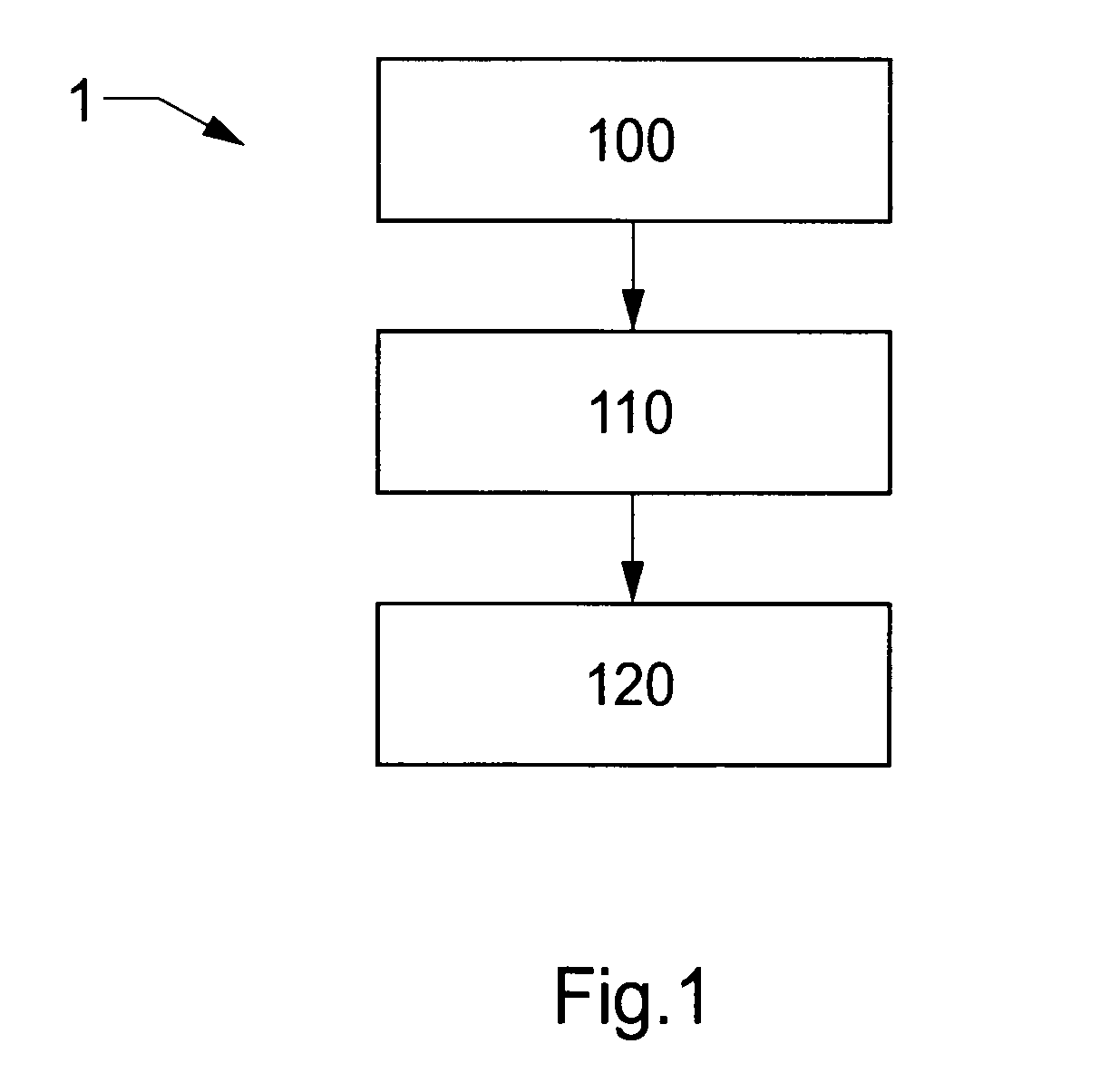
Bone resorption in edentulous subjects provides a challenge in many aspects of dental restorative procedures.
However, in edentulous subjects a defined, stable position of the surgical template may be not given, e.g. due to bone resorption of the alveolar ridge.
Furthermore, there may be no unambiguous anatomical structure in the oral cavity giving a clear-cut positioning of the surgical template in the subject.
Positioning of the real surgical template manufactured based on data of the virtual planning is thus difficult.
This may inherently lead to a non-desired positioning of implants in the subject, and thus non-desired results of surgical restorative procedures, such as dental restorative procedures.
However, the method disclosed in US2007077535 is purely model based, and has a number of drawbacks.
For instance, a surgical template is produced in a conventional model-based manner, whereby sources of errors as conventionally known are not eliminated, e.g. shrinkage of each of an impression material and subsequently of a casting material for a surgical template cast form and finally the material of the surgical template in the cast are contributors to an error chain, whereby accuracy is lost in each process step.
This lack of accuracy may not be acceptable in some medical procedures.
Therefore, the method disclosed in US2007077535 may not work satisfactory, in particular for critical applications, such as implantation of zygoma implants.
Further, a mass customization of surgical templates to be used in dental restorative procedures is not feasible according to the method disclosed in US2007077535.
Each single surgical template needs an enormous amount of manual adaptation on physical casts and models.
An issue is that acrylic material used for producing radiographic guides from dental impressions is shrinking when it polymerizes.
However, in order to provide a practically implementable virtual planning, it may also be necessary to provide a second input data set for the master structure, e.g. providing data for portions that are non-radiopaque and do not provide useful data for generating the first data set based on the first input data.
However, in practice a metal object in the scan structure such as dental fillings, metal bridges, copings, etc. may lead to streak artefacts rendering the generated data unsuitable for a precise virtual planning of a surgical procedure and subsequent production of components based on the virtual planning.
These artefacts may cause serious problems during the virtual planning as they may obscure the dental arches in the CT scan, as for it may be impossible to distinguish between the radiopaque material including barium sulfate in the radiographic guide and the streak artefacts.

Method used


Image

  • Repositioning of components related to cranial surgical procedures in a patient
  • Repositioning of components related to cranial surgical procedures in a patient
  • Repositioning of components related to cranial surgical procedures in a patient

Examples


example 1

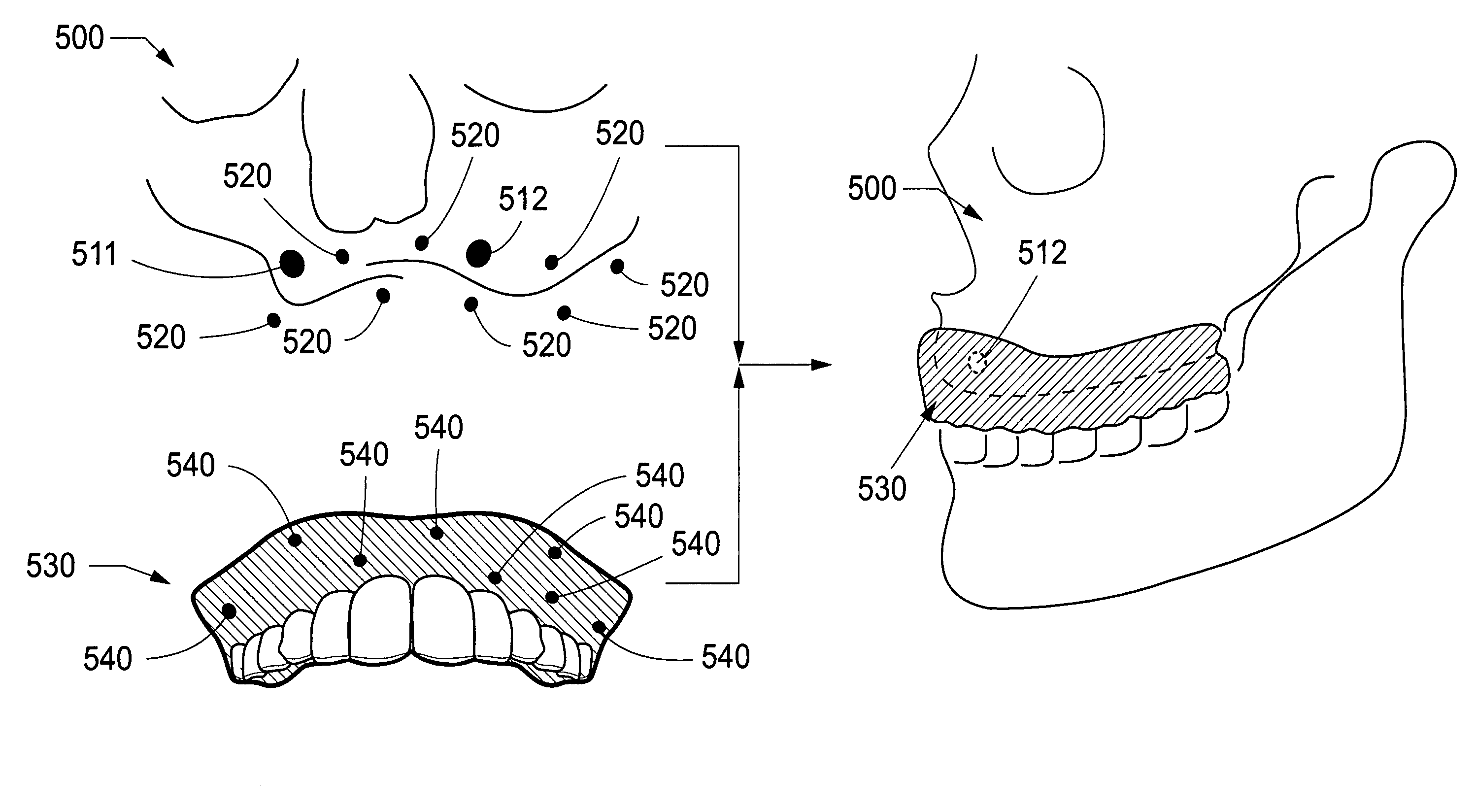
[0187]a) A surgeon positions at least one temporary anchoring implant (reference structure) into jaw bone tissue that only a top part of the head section thereof protrudes into the soft tissue.[0188]A radiographic guide (master structure) in form of a duplicate prosthesis with gutta percha markers is put into position, and slid over the head section in the soft tissue, such that the master structure has a defined relation to the reference structure.[0189]c) A first CT scan is performed with the patient wearing the radiographic guide and a radiographic index, providing a first set of data. The first scan may be performed with a low dosage CT scanner to minimize radiation impact on the patient.[0190]d) A second CT scan of the radiographic guide only is performed, providing a second set of data.[0191]e) Virtual planning of the dental restoration and medical procedure is performed, providing production data for a surgical template based on an associated data set of said first data set a...

example 2

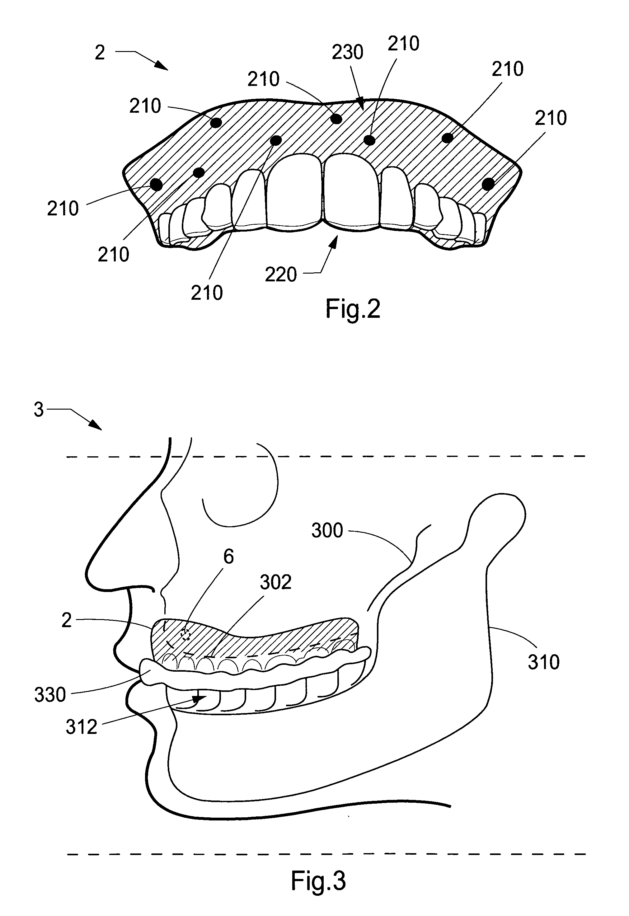
[0199]a) an OPG of the subject is taken, with radiopaque markers to define reference points in the flange, e.g. two markers positioned at the top edge of the prosthesis in order to identify position of jaw bone tissue in relation to the prosthesis[0200]b) the prosthesis of the patient is duplicated, e.g. from an impression made thereof providing a form for casting in a cold acrylic material, providing a duplicate prosthesis for use as a radiographic guide[0201]c) either at least one anchor screw are provided in the radiographic guide, via corresponding through holes thereof, or at least one temporary anchor implant is screwed into jaw bone tissue at a suitable position thereof, and the radiographic guide is suitably matched to possible protruding parts of the proximal end of the temporary anchor implant by creating suitable recesses in the radiographic guide, such that it fits into place over the protruding part

[0202]Alternatively, or in addition to step a) described above, bone pos...

example 3

[0203]a) at least one temporary anchor implant is inserted into jaw bone tissue of a patient[0204]b) a dental impression of the patient is made with a triple tray[0205]c) A CT scan is made of the patient wearing the triple tray and the dental impression therein, wherein the triple tray is provided with fiducial markers, e.g. of gutta percha—providing a first data set for the position and direction of the temporary anchor implant as well as the dental impression in relation thereto[0206]d) the dental impression is converted to a second data set, e.g. by means of a 3D scanner, such as a touch probe scanner or an optical scanner, wherein the position of the fiducial markers is provided by a suitable geometrical form thereof, which is registered by the 3D scanner[0207]e) the first and second data set are associated as described above, providing a third data set for production of a surgical template.

[0208]In case the temporary anchor implant or anchor screw is provided at a position wher...


PUM


Abstract

Methods, systems, and computer-readable media are disclosed herein for virtually planning a cranial guided surgery in a subject. These include, in some embodiments, generating a first data set based on input data obtained of a reference structure having a defined fixed relation to a bone structure of said subject and generating a second data set based on input data obtained of a master structure for a surgical template, where the master structure has a defined relation to said reference structure. Further, in some embodiments, a third data set for production of said surgical can be generated based on the first data send and the second data set, wherein the relation of said reference structure to said master structure is preserved.

Description

CROSS-REFERENCE TO RELATED APPLICATIONS[0001]This application is a national stage application under 35 U.S.C. §371 of PCT Application No. PCT / EP2009 / 001931 designating the United States, filed on Mar. 17, 2009 and claiming priority to European Patent Application No. 08005146, filed on Mar. 19, 2008. The PCT Application was published in English as WO 2009 / 115283 A1 on Sep. 24, 2009, and claims the benefit of the earlier filing date of European Patent Application No. 08005146.9, filed on Mar. 19, 2008. The contents of PCT Application No. PCT / EP2009 / 001931, including publication WO 2009 / 115283 A1, and European Patent Application No. 08005146.9, are incorporated herein by reference in their entirety for all purposes.FIELD OF THE INVENTION[0002]This invention pertains in general to the field of cranial surgery, including dentistry. More particularly the invention relates to a method and system for repositioning of components in relation to a patient during cranial surgical procedures, in...

Claims


Application Information

Patent Timeline
Patent Type & Authority Applications(United States)
IPC IPC(8): G06F17/50
CPCA61B17/176A61B17/8625A61B17/8685A61C1/084A61C13/225A61C8/0096A61C8/0098A61C13/0004A61C8/0089G16H20/40
Inventor PETTERSSON, ANDREASBRAJNOVIC, IZIDORPETERSSON, HENRIK
Owner NOBEL BIOCARE SERVICES AG
Why Eureka
Try Eureka